An Introduction to eSIM Technology
- 22 Oct, 2026
This article, drawing from engineering practices with 5G RedCap modules such as the Quectel RG255C-NA00AB, offers a systematic and comprehensive in-depth analysis and technical summary of eSIM (Embedded SIM) technology. It covers the entire process from hardware packaging, underlying protocols, and core concepts to initial network provisioning, dynamic profile switching, and Remote SIM Provisioning (RSP).
eSIM Card Physical Form Factor and Hardware Implementation Solutions
In the engineering application of eSIM, the most common misconception that needs to be dispelled first is that “eSIM” does not entirely transform a SIM card into pure software code. Instead, it encompasses both the evolution of hardware form factors and the upgrade of software architecture.
eSIM Physical Form Factor (MFF2) and Software Architecture (eUICC)
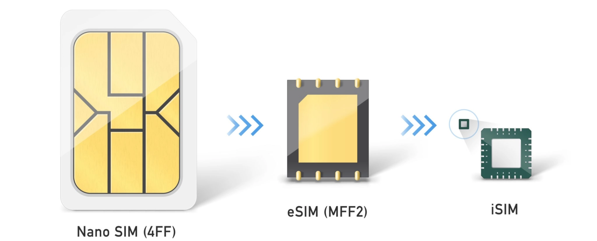
- Hardware Form Factor (MFF2 Package): Traditional consumer or industrial plug-in SIM cards use form factors like Nano SIM (4FF), requiring a mechanical card slot. In an eSIM solution, the physical carrier is an industrial-grade surface-mount chip compliant with JEDEC standards, utilizing an MFF2 package (SON-8 / DFN-8), with dimensions of only 5mm × 6mm × 0.75mm. It is directly soldered onto the PCB via Surface Mount Technology (SMT). Electrically, eSIM is almost identical to a traditional external SIM card slot. Whether externally mounted on the module or integrated internally, it still uses the standard ISO/IEC 7816 interface protocol, connecting to the RG255C module’s
USIM_VDD(power supply 1.8V/3.0V),USIM_CLK(clock),USIM_DATA(data I/O), andUSIM_RST(reset). - Software Architecture (eUICC): Inside the chip, an eUICC (Embedded UICC) operating system runs, compliant with GSMA standards. It not only possesses the secure storage area of a regular SIM card but also offers Remote SIM Provisioning (RSP) capabilities to dynamically download, store, activate, and delete multiple operator profiles.
Why Do Traditional Plug-in SIM Cards Present Significant Pain Points in Product Applications?
In 5G security cameras deployed at high altitudes outdoors, traditional physical card slots pose serious engineering risks:
- Poor structural reliability: Long-term exposure to wind, sun, and strong vibrations outdoors (e.g., traffic checkpoints, vehicle monitoring, tower crane monitoring) can cause the spring contacts of mechanical card slots to suffer from fatigue deformation, fretting, or even momentary power loss, leading to a
SIM Not Founderror reported by the baseband module. - Limited water and dust resistance: The casing must incorporate a rubber waterproof plug to accommodate the SIM card maintenance access, increasing the risk of water ingress and moisture penetration.
- High security risk: Malicious individuals can easily open the camera casing to remove the SIM card and steal data. By adopting MFF2 surface-mount eSIM, the chip is integrated with the mainboard, completely eliminating physical SIM card theft.
Two Major Hardware Implementation Solutions for eSIM and Selection Comparison
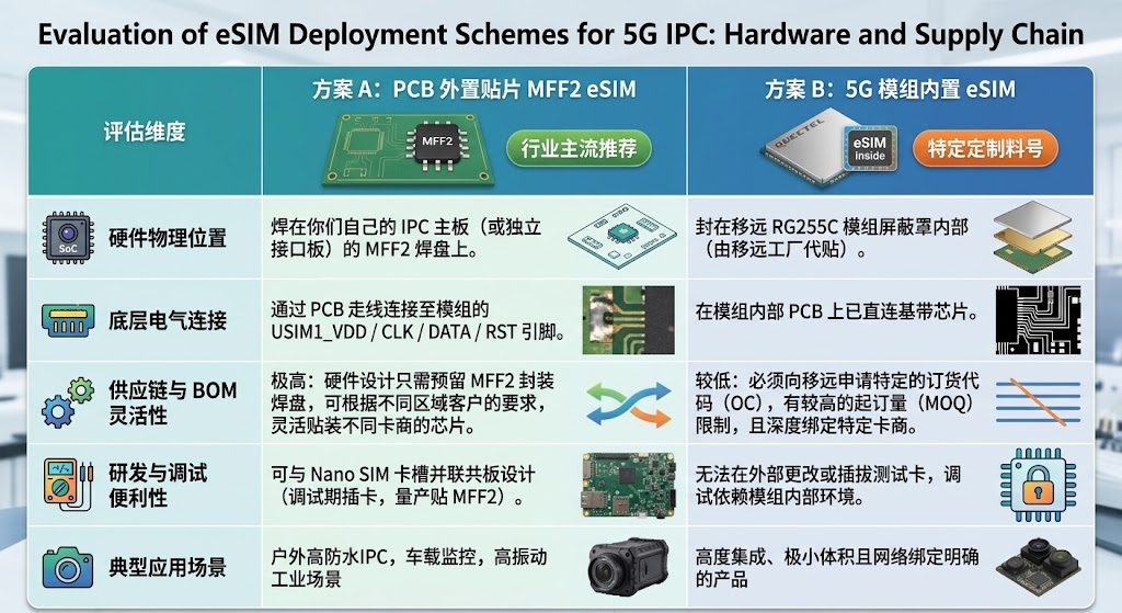
When designing 5G IPC mainboards equipped with Quectel RG255C-NA series modules, we face two distinctly different physical implementation paths:
Key Design Considerations for Hardware Schematics
If Solution A (mainboard external surface-mount MFF2 eSIM) is adopted, its peripheral hardware circuit is identical to that of a traditional physical SIM card. However, the following signal integrity aspects require particular attention during design:
- ISO/IEC 7816 Interface Specification: The
USIM_CLK(clock line) typically operates at 3MHz~5MHz. Its routing must be kept away from high-frequency RF antennas (e.g., 5G Sub-6GHz main antenna, Wi-Fi antenna) to prevent high-frequency coupled noise from causing SIM card clock distortion. - ESD Protection: Since the MFF2 chip is often located near the board edge or exposed to complex environments, low-capacitance (≤ 5pF) dedicated SIM card electrostatic protection diodes (ESD Arrays) must be placed close to the
USIM_DATA,USIM_RST,USIM_CLK, andUSIM_VDDtraces, meeting the IEC 61000-4-2 Level 4 contact discharge standard. - Power Filtering:
USIM_VDDmust provide a clean 1.8V/3.0V switchable power supply. A 100nF high-frequency decoupling capacitor must be paralleled near the chip pins.
Core Concepts and Terminology Related to eSIM Cards, and LPA Deployment Analysis
To fully understand eSIM’s Remote SIM Provisioning (RSP) mechanism, it is crucial to clearly define four core terms within the GSMA standard framework and clarify the underlying control logic.
Four Core Concepts and Terms of eSIM
- EID (eUICC Identifier): The globally unique 32-digit identification number burned into the hardware secure area of each eSIM (eUICC) chip during factory production. It serves as the sole credential for the cloud-based provisioning server to identify a specific device (similar to a hardware MAC address).
- Profile: Can be understood as a “software-based virtual SIM card data package.” It contains all the sensitive core elements of a traditional physical SIM card: International Mobile Subscriber Identity (IMSI), Integrated Circuit Card Identifier (ICCID), network authentication root keys (Ki / OPc), and the operator’s PLMN priority list and APN configuration. At any given time, an eUICC chip can store multiple Profiles, but only one (or a very few specific scenarios) is allowed to be in an Enabled (active) state, while the others remain in a Disabled (inactive) state. This point is crucial for understanding the eSIM workflow.
- SM-DP+ (Subscription Manager Data Preparation+) Server: A “card provisioning and encrypted packaging server” deployed in the cloud by mobile network operators or third-party Mobile Virtual Network Operators (MVNOs). It stores all operator key libraries via Hardware Security Modules (HSMs). Upon receiving a device’s download request, it generates and encrypts a dedicated Profile for that device’s EID in real-time.
- LPA (Local Profile Assistant): An agent control program running on the device side (typically within the 5G module). Its core responsibilities are: proactively initiating HTTPS/TLS connection requests to the SM-DP+ server, receiving encrypted Profile data packages, and writing them into the eUICC chip’s secure storage area via standard APDU commands, while also managing Profile enablement, disablement, and deletion.
Where Does the LPA Run, and Why?
Under the hardware architecture of embedded Linux + Quectel 5G modules, the LPA’s deployment location directly determines the software team’s workload:
- Mainstream Mode: LPA runs inside the Quectel 5G module (Modem-based LPA). For the RG255C-NA series modules, their internal baseband firmware already integrates an LPA engine compliant with GSMA SGP.22 / SGP.32 standards. The embedded Linux system running on the product’s main control SoC (e.g., Rockchip, Ingenic, or Ambarella platforms) does not require porting any complex LPA source code or TLS stack at all.
- Engineering Architecture Advantages: When a Profile needs to be downloaded or switched, the Linux main controller only needs to send simplified, dedicated AT commands (e.g.,
AT+QESIM="download", "LPA:1$smdp.address$matching_id") to the Quectel module via a serial port (e.g.,/dev/ttyUSB2). The subsequent heavy tasks of HTTPS mutual certificate handshake, TLS data decryption, and sending APDU fragmented write commands to the eUICC via the ISO 7816 bus are all automatically completed by the Quectel module’s internal baseband. This greatly ensures system stability and R&D efficiency.
Complete Breakdown of eSIM’s Initial Connection and Profile Download Process
In eSIM projects, the most classic architectural problem is: “If a newly manufactured eUICC chip contains no operator data, how can the device connect to the 5G cellular network? And if it can’t connect to the network, how can it download the official operator Profile from the cloud-based SM-DP+ server?”
To break this “chicken or the egg” network deadlock, eSIM employs an ingenious Bootstrap Profile mechanism.
The Core Mechanism of Bootstrap Profile Guidance
- What is a Bootstrap Profile? In MFF2 eSIM chips procured by card vendors, a special Bootstrap Profile is pre-provisioned inside the chip by the chip manufacturer during the wafer-level factory testing (Personalization) phase.
- Is it a single operator or multiple operators? From a data structure perspective, this Bootstrap Profile is just one independent Profile within the eUICC (typically belonging to a multinational roaming MVNO). However, in terms of signaling access capability, the issuer has pre-signed rigorous international/inter-network roaming agreements with major operators. Therefore, it is internally configured with an extensive PLMN preferred network list, allowing it to connect to different operator base stations via roaming.
- Actual Power-on Behavior: When the IPC hardware is powered on for the first time, the RG255C module reads this active Bootstrap Profile and automatically scans the surrounding electromagnetic environment. Regardless of whether nearby base stations belong to AT&T or T-Mobile, it can successfully register as a roamer and obtain a weak cellular data channel.
Cloud Profile Download Process Initiated by Bootstrap
The diagram below illustrates the complete process, using a 5G IPC as an example, from the initial power-on of the IPC and its 5G module starting with the Bootstrap Profile to the download of the official Profile version:
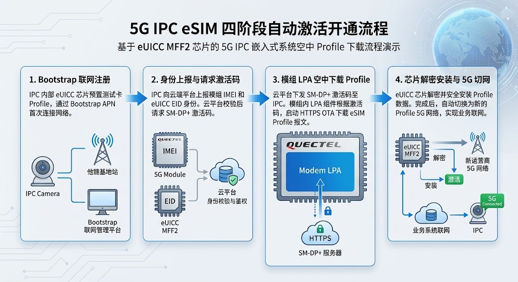
- Phase 1 (Bootstrap Network Registration): The IPC camera powers on for the first time, uses its pre-installed Bootstrap ID to successfully register with a local base station, obtain an IP address, and connect to the internet.
- Phase 2 (Device Identity Reporting and Activation Code Acquisition): The IPC main controller connects to the IPC business cloud backend via its built-in MQTT or HTTPS client, reporting the device’s hard-coded
SNand the 32-bit globally uniqueEIDread from the eSIM. The IPC backend server accesses the card vendor’s CMP (Connectivity Management Platform) via REST API. The card vendor then locks a dedicated North American local official Profile (e.g., a T-Mobile business plan) for thatEIDon the backend SM-DP+ server and returns an Activation Code in text format, which also includes the SM-DP+ server’s URL address. - Phase 3 (Module LPA Over-the-Air Download): The IPC backend sends this activation code string to the camera’s Linux main controller. Linux then transparently transmits it to the Quectel RG255C module via a serial port. The module’s internal LPA engine parses the SM-DP+ server address, bypasses the business backend, directly establishes a TLS encrypted session with the cloud, and uses the activation code to pull the dedicated encrypted Profile data package.
- Phase 4 (On-chip Decryption and Seamless Network Switch): The RG255C writes the encrypted data to the eUICC chip’s secure area via the USIM physical bus (APDU commands). After the chip internally completes decryption and verification, the main controller sends an AT command to Enable the new Profile. The module then soft-restarts the USIM interface, discards the Bootstrap, and formally connects to the local North American operator’s 5G high-speed network.
Dynamic Profile Updates and Cross-Region No-Network Fallback Mechanism in eSIM
In real-world project deployments, such engineering challenges are frequently encountered: a 5G IPC that was activated and bound to an official Verizon Profile in Texas, USA, is later uninstalled by the customer and redeployed to a remote farm – a new location where only T-Mobile base stations have coverage, with no Verizon signal at all. What happens then?
Without any software fallback mechanism, the device would enter a fatal “deadlock”:
- The eUICC chip currently has the Verizon Profile activated. In the new location with no Verizon signal, the module cannot register with a base station.
- Since there’s a complete network outage, the cloud backend cannot contact this IPC, nor can the IPC itself initiate an HTTPS request to download the T-Mobile Profile. The device becomes “bricked”.
To ensure device self-recovery during relocation or base station changes, the industry has developed three mature software architecture solutions:
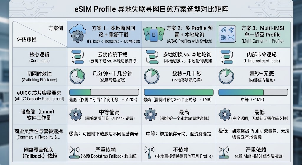
Overall, this is still limited by the fact that only one Profile can be active in an eSIM at any given time. Therefore, essentially, this process involves switching to the Bootstrap or another available built-in Profile after a period of network outage to try and restore network access capability.
Summary of eSIM Core Component Collaboration and the Full Remote SIM Provisioning Process
Synthesizing all the aforementioned hardware interfaces, protocol standards, and disaster recovery logic, we can summarize the system-level collaborative relationships of the entire eSIM solution into the following complete panoramic architectural blueprint:
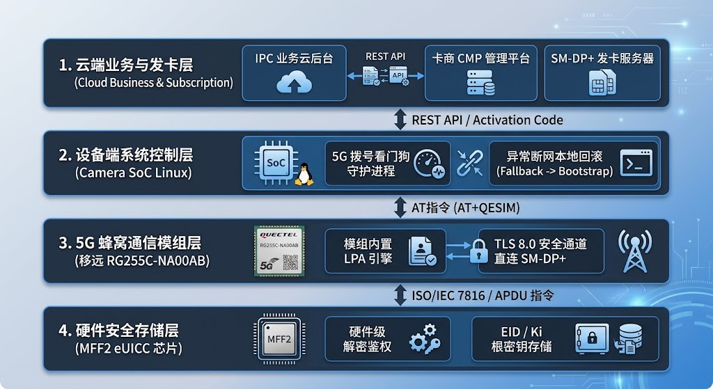
Neither the business cloud backend for hardware products nor the Linux memory running on the Camera SoC will ever handle or be allowed to store any plain-text or encrypted core Profile assets (such as Ki keys). All sensitive decryption and authentication actions are strictly locked within the closed loop of the operator’s cloud-based HSM (Hardware Security Module) and the eUICC chip’s hardware secure area on the device side.
Furthermore, leveraging the native LPA capability embedded in the Quectel RG255C module, complex underlying TLS handshakes and APDU interactions are completely abstracted from Linux developers. The project team only needs to focus on: anti-interference design for MFF2 package pads and the USIM bus on the PCB hardware, and watchdog timeout monitoring and Bootstrap fallback strategies for out-of-network scenarios at the Linux application layer.
Through this comprehensive set of hardware-software collaborative designs, 5G IPC projects can achieve both the supply chain flexibility of traditional physical cards and the ultimate environmental reliability brought by eSIM, enabling efficient, stable, and scalable commercial deployment in the demanding industrial and security markets of North America.