Summary of Learning TI's Impedance Track Battery Fuel Gauging Technology
- 22 Jun, 2020
Key Parameters for Batteries and Fuel Gauges:
- QMax: Total chemical capacity of the battery;
- OCV: Open Circuit Voltage, the open-circuit voltage output by the battery;
- The battery voltage when the battery is in a Relaxation state (at very low current) is typically considered as the OCV.
- DOD: Depth of Discharge;
- The fuel gauge contains an internal lookup table between Depth of Discharge (DOD) and Open Circuit Voltage (OCV). In an open-circuit, no-load state, this table can be used to accurately determine the battery’s discharge status.
- The DOD calculated by the fuel gauging algorithm determines whether the current battery internal resistance parameters should be updated, and when to begin calculating and updating RM/FCC.
- SOC: State of Charge, which is essentially the percentage of remaining battery power;
- The specific calculation formula is
SOC = Q / QMax = RM / FCC;
- The specific calculation formula is
- RM: Remaining Capacity, the remaining capacity of the battery;
- Remaining capacity calculations occur immediately after discharge onset, at every resistance update, and after entering relaxation mode.
- FCC: Full-Charge Capacity, the usable capacity of the battery when fully charged;
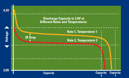
- FCC is actually the total capacity released by the battery when it is fully charged and discharged at a certain rate down to the cut-off voltage. In reality, some capacity, known as Reserve Capacity, still remains within the battery at this point.
- It is related to the discharge rate and current temperature. The faster the discharge rate and the lower the temperature, the smaller the FCC, because the presence of battery internal resistance in these conditions causes the battery to reach the cut-off voltage more quickly.
- Ra: Battery Internal Resistance Parameter
- The battery internal resistance varies with different depths of discharge; the lower the battery charge, the higher the internal resistance, reaching its maximum when approaching the battery’s cut-off voltage.
- During the calibration process, the fuel gauge automatically calculates 15 sets of battery internal resistance parameters, Ra0-Ra14, based on the battery’s characteristics. These resistance parameters are dynamically updated during the operation of the Impedance Track algorithm.
- The formula for calculating battery internal resistance is: (OCV - BatteryVoltageUnderLoad) / AverageLoad Current;
Factors Affecting Fuel Gauge Calculation
-
Load Conditions
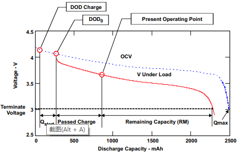
- In the figure below, the solid and dashed lines represent the battery voltage-capacity curves under certain load conditions and no-load conditions, respectively;
-
Temperature
-
Charge/Discharge Cycles (Aging)
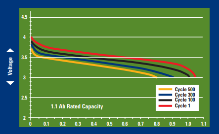
- The internal capacity of the battery gradually decreases with an increasing number of charge/discharge cycles, which is the aging phenomenon observed during battery use.
Fuel Gauge Calculation Mode Switching
Three fuel gauge calculation states: Relaxation, Charging, Discharge.
Three current thresholds: Quit Current Threshold, Charge Current Threshold, Discharge Current Threshold.
Three Relax Times: Charge Relax Time, Quit Relax Time, Discharge Relax Time.
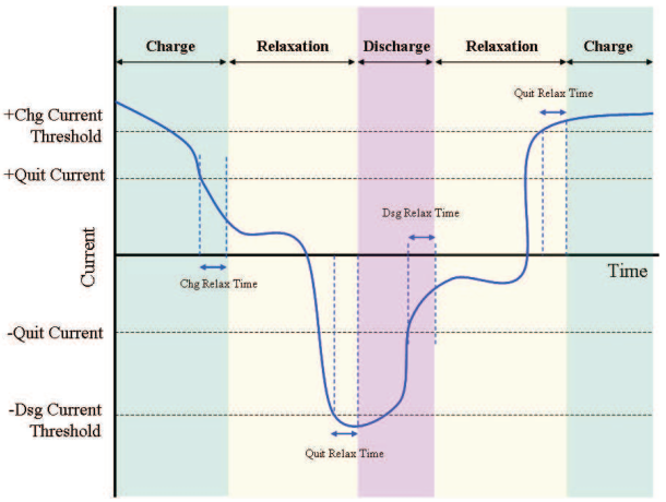
- When the fuel gauge calculation mode is in Charging mode: If the average current detected by the fuel gauge is less than the Quit Current Threshold, and this condition is maintained for a duration greater than Charge Relax Time, the fuel gauge calculation mode switches from Charging mode to Relaxation mode;
- When the fuel gauge calculation mode is in Relaxation mode: If the average current detected by the fuel gauge is greater than the Discharge Current Threshold, and this condition is maintained for a duration greater than Quit Relax Time, the fuel gauge calculation mode switches from Relaxation mode to Discharging mode;
- When the fuel gauge calculation mode is in Discharging mode: If the average current detected by the fuel gauge is less than the Quit Current Threshold, and this condition is maintained for a duration greater than Discharge Relax Time, the fuel gauge calculation mode switches from Discharging mode to Relaxation mode;
- When the fuel gauge calculation mode is in Relaxation mode: If the average current detected by the fuel gauge is greater than the Charge Current Threshold, and this condition is maintained for a duration greater than Quit Relax Time, the fuel gauge calculation mode switches from Relaxation mode to Charging mode;
Assessing Battery Depth of Discharge (DOD) in Different Modes
In the Relaxation state, after the battery has been in Relaxation mode for more than 30 minutes, the voltage change is monitored. If the condition dv/dt < 4uV/s is met (meaning the battery voltage change is minimal), the fuel gauge measures the battery’s open-circuit voltage every 100 seconds. It then calculates the current DOD based on the built-in OCV-DOD curve and updates it to the DOD0 parameter, while simultaneously resetting the PassedCharge parameter to 0;
- During this process, if the current flowing through the fuel gauge is not zero, an IR compensation needs to be applied to the read OCV: The battery internal resistance parameter Ra corresponding to the current DOD is looked up, and then the corrected OCV’ (
OCV' = OCV - I * Ra) is used to consult the OCV-DOD curve to calculate the current DOD;
When the battery is in a Charging or Discharging state, the current Depth of Discharge (DOD) is calculated using the following formula:
DOD = DOD0 + PassedCharge / QMax;
- DOD0 is the last updated DOD parameter when the battery was in the Relaxation state. PassedCharge is also reset to 0 when the DOD parameter was last updated, and begins accumulating the charge passed through the fuel gauge from that point;
- In essence, the correspondence/lookup table between battery OCV and DOD is built into the fuel gauge chip, which is referred to as the Chemistry Profile. For the BQ27426, this fuel gauge chip has 3 built-in Chemistry Profiles (i.e., predefined discharge curves for the fuel gauge), corresponding to standard 4.2V, 4.35V, and 4.4V lithium batteries, respectively. The desired Chemistry Profile can be read and set via the ChemID command. For some relatively special lithium batteries, TI’s BQ2750x series fuel gauge chips support custom fuel gauge curves by writing a .senc fuel gauge parameter file.
QMax Update
QMax is calculated after two independent DOD updates (meaning there must be a Charge or Discharge state between these two DOD updates);
- That is, DOD1 is measured and saved in the Relaxation state, then the battery enters a Charge or Discharge state, and after re-entering the Relaxation state and completing the new DOD2 measurement, QMax is updated based on the following formula:
QMax = PassedCharge / |DOD2 - DOD1|;- PassedCharge is the amount of charge passed through the fuel gauge, measured by the coulomb counter between the two DOD update calculations;
- When updating DOD1 and DOD2, it is crucial to ensure that the fuel gauge is in a deep Relaxation state, meaning it has entered the Relaxation state for more than half an hour, and the condition
dv/dt < 4uV/sholds true;
To ensure the accuracy and precision of the QMax update calculation, the updates mentioned above will not occur if the temperature is above 40 degrees Celsius or below 10 degrees Celsius. Updates will also not occur if one of the voltages for DOD1 or DOD2 is between 3737mV and 3800mV.
Battery Internal Resistance Ra Update
Battery internal resistance is calculated and updated when the battery is in a Discharge state.
Calculate the internal resistance parameter for the current DOD using the following formula:
dV = V - OCV(DOD, T)R(DOD) = dV / I
In the formulas above, V is the battery voltage measured in the current discharge state, and OCV(DOD, T) is the open-circuit voltage obtained by looking up the battery’s internal curve based on the current DOD;
The battery internal resistance parameters mentioned above are continuously calculated and stored in memory while the battery is in a discharge state. They are written to Data Flash when the DOD state reaches the following nodes:
Index   SOC    DOD
Ra 0  100%      0
Ra 1  88.9%     11.1%
Ra 2  77.8%     22.2%
Ra 3  66.7%     33.3%
Ra 4  55.6%     44.4%
Ra 5  44.5%     55.5%
Ra 6  33.4%     66.6%
Ra 7  22.3%     77.7%
Ra 8  19%        81%
Ra 9  15.7%     84.3%
Ra 10 12.4%    87.6%
Ra 11 9.1%      90.9%
Ra 12 5.8%      94.2%
Ra 13 2.5%      97.5%
Ra 14 0%        100%
Calculation and Update of RM, FCC, and SOC
RM (Remaining Capacity) is calculated using Voltage Simulation. The general process is:
Starting from the current DOD, i.e., DODStart:
DODStart = DOD0 + PassedCharge / QMax;
- DOD0 is the Depth of Discharge measured based on the battery’s open-circuit voltage when it was last in deep Relaxation mode;
- PassedCharge is the amount of charge passed through the fuel gauge, calculated starting from the last DOD0 measurement;
Simulate and calculate the discharge curve under load conditions based on the following formula:
V(DODx, T) = OCV(DODx, T) + I × R(DODx, T)
- DODx starts from DODStart and increases incrementally at a step rate of 4% for curve calculation;
- OCV(DODx, T) is the corresponding open-circuit voltage obtained for that DOD and temperature state;
- I is the current load current;
- R(DODx, T) is the corresponding battery internal resistance for that DOD and temperature state;
- V(DODx, T) is the simulated calculated voltage under load for that DOD and temperature state;
Refer to the figure below to understand the calculation process:
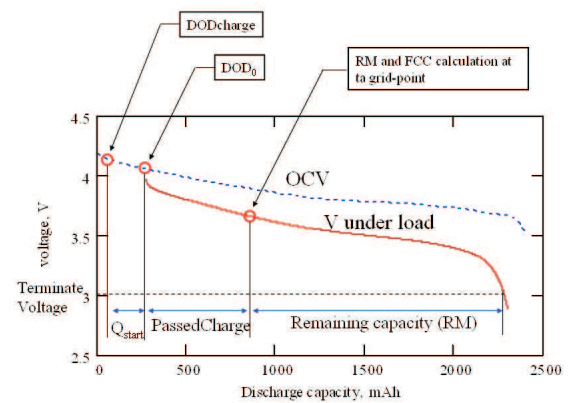
By calculating using the simulated curve above, when the calculated V(DODx, T) equals the battery’s cut-off voltage, the corresponding DOD found by querying the battery’s OCV discharge curve at that point is what is known as DODFinal.
RM = (DODFinal - DODStart) * QMax;
FCC comprises three parts:
FCC = QStart + PassedCharge + RM.
- QStart is the amount of charge consumed by the battery from a full charge state to the DOD0 state;
- PassedCharge is reset to 0 when DOD0 is updated, and accumulates the charge passed through the fuel gauge from that moment;
- RM is the remaining capacity calculated according to the voltage simulation formula above;
The calculation formula for SOC is as follows:
SOC = RM * 100 / FCC.
This continuously updated and calculated SOC is the final battery percentage displayed to the user.
References:
- SLUA450: Theory and Implementation of Impedance Track Battery Fuel-Guaging Algorithm in BQ2750x Family;
- SLUA375: Impedance Track Gas Gauge for Noices;