Summary of Audio Interfaces in Consumer Audio Codecs
- 06 Apr, 2025
Based on a study and summary of the datasheet for the commonly used TLV320AIC3101 Audio Codec in the market, this article delves into the input/output interfaces of general audio codecs and their internal signal processing flows, establishing a more comprehensive understanding of audio codecs and their audio processing pipelines.
The full text is divided into three parts:
- Analog Audio Input Interfaces
- Analog Audio Output Interfaces
- Digital Audio Interfaces
Introduction to Analog Audio Input Interfaces
Taking the TLV320AIC3101 as an example, this Audio Codec supports 6 single-ended analog audio input pins, including 2 fully differential inputs (offering strong noise immunity, suitable for long-distance microphone connections) and 2 single-ended inputs (simplifying circuit design). Through internal register configurations and external circuitry, it can be set to work in single-ended microphone, differential microphone, and single-ended/differential Line In operating modes.
The figure below shows a simplified block diagram of the TLV320AIC3101. For analog audio inputs, the standard approach is: if single-ended microphones are used, two independent left and right channel single-ended microphones can be connected via L2_L and L2_R. If differential microphones are used, two independent left and right channel differential microphones can be connected via L1_L+, L1_L- and L1_R+, L1_R- respectively.
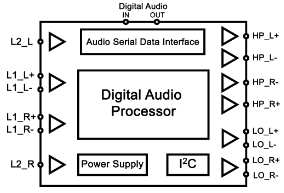
Of course, the differential-mode pins L1_L and L1_R can also be used as single-ended microphone interfaces, allowing up to 6 single-ended microphones to be connected simultaneously.
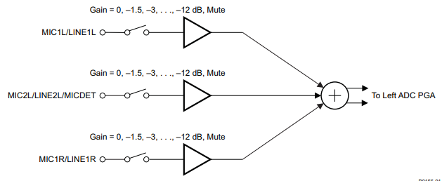
However, it should be noted that the TLV320AIC3101 has only 2 internal ADCs, which can process two analog audio data streams in parallel simultaneously. Therefore, if more analog audio inputs are connected at the same time, they must share the same ADC by multiplexing across multiple audio data channels. Since the audio sampling rate is configured at the ADC, having multiple audio inputs share a single ADC results in a reduced actual sampling rate per channel. For example, a single ADC supports a maximum sampling rate of 96 kHz; if 3 inputs are activated simultaneously, the sampling rate for each analog audio input drops to just 32 kHz.
The diagram below illustrates multiple analog audio inputs sharing a single ADC in the TLV320AIC3101, where three analog audio input pins—MIC1L/LINE1L, MIC2L/LINE2L/MICDET, and MIC1R/LINE1R—share the same Left ADC.
Mic In
Mic In is the operating mode for connecting analog microphone signals, and it is also the most common analog audio input mode for Audio Codecs.
The typical peak-to-peak input signal voltage for electret microphones commonly used in our products generally ranges from 10 mV to 100 mV, whereas the ADC input range is typically designed to be ±1 V (fully differential) or 0–2 V (single-ended). Therefore, before ADC conversion, the microphone output signal must first pass through a preamplifier to boost its signal level, maximizing the dynamic range of the ADC conversion signal level.
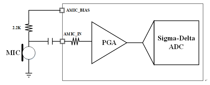
Additionally, to allow electret microphones to function properly, the Audio Codec must also supply power to the electret microphone via the MICBIAS pin (the typical supply voltage for MICBIAS on the TLV320AIC3101 is 2V–2.5V). The typical connection for supplying power to an electret microphone via MICBIAS involves routing the MICBIAS voltage through a resistor (such as 2.2 kΩ) to the positive terminal of the microphone, forming a current loop (with a typical current of about 0.5 mA).
The diagram below shows a single-ended microphone connection:
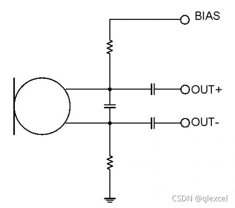
To further improve the noise-reduction performance of captured microphone signals, a differential connection method can be used to suppress common-mode noise to the greatest extent possible:
Line In
The Line In interface (along with the Line Out interface for outputs) is used to interface with other consumer electronic devices or professional audio equipment.
The TLV320AIC3101 provides two sets of Line In interfaces, which also support both single-ended and differential input modes, configured via registers. In single-ended input mode, the peak-to-peak voltage () ranges from 0.5 V to 2 V (exceeding the supply voltage must be avoided during interfacing); in differential input mode, the range is 1 V to 4 V (with the common-mode voltage required to be within ). Therefore, when operating in Line In mode, the voltage dynamic range is already close to the full-scale input of the ADC, meaning no preamplification is required. Only appropriate gain fine-tuning within the PGA is necessary—this is what sets Line In mode apart from MIC In mode.
Furthermore, when using Line In, there is no need to supply power to the upstream device of the Line In signal via MICBIAS, which is another key difference between the two.
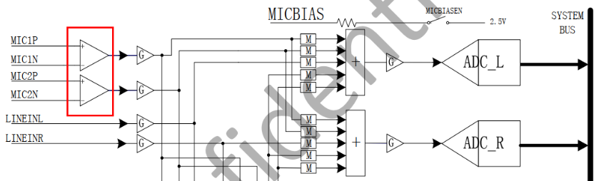
The diagram below illustrates the differential connection of Mic In and Line In for the Allwinner H3 platform Audio Codec.
Introduction to Analog Audio Output Interfaces
Just as an Audio Codec has analog input interfaces (MIC, Line In), it naturally has analog output interfaces (Line Out, HPOUT). Generally speaking, the analog output interfaces of an Audio Codec are used to amplify the analog audio signals converted by its internal DAC via audio power amplifiers, in order to drive speakers of varying power levels, headphones, or to feed downstream professional audio equipment via Line Out.
Most Audio Codecs contain two main types of analog audio output interfaces:
- HPOUT: Includes a small power amplifier following the DAC output of the Audio Codec, allowing it to directly drive headphones and low-power speakers.
- Line Out: Essentially the raw DAC output of the Audio Codec without internal power amplification, making it suitable for connecting to a subsequent power amplifier stage to drive higher-power speakers.
Line Out
Regarding analog audio output interfaces, the Line Out interface is suitable for connecting high-impedance equipment, such as professional audio mixing consoles and power amplifiers driving larger speakers. The peak-to-peak output voltage of this interface generally ranges between 1 V and 2 V, characterized by high input impedance, low output impedance, and very low output current (), making it ideal for high-impedance loads ().
Taking the TLV320AIC3101 as an example, this Audio Codec contains two sets of independently configurable, fully functional differential Line Out interfaces, both capable of driving 10 kΩ differential loads. The analog audio signals output from the DAC undergo flexible audio signal path control, are mixed with multiple voice signals from different sources in the mixing module, undergo gain adjustment, and are finally output as differential audio signals. Below is the block diagram of the Line Out output structure for the TLV320AIC3101.
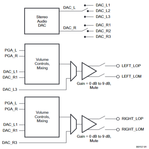
- The analog audio signals output by the left and right channel DACs are connected via register configurations to
DAC_L1/2/3andDAC_R1/2/3, respectively. - When mixing functionality is required in the analog audio output,
DAC_L1andDAC_R1(DAC_L2andDAC_R2are used for HPOUT output), along with the PGA-amplified ADC input signals from the analog input side (PGA_L/PGA_R—allowing analog audio signals entering the Audio Codec to bypass the ADC-DAC processing loop after PGA amplification and go directly to the analog audio output stage), are fed into two independent Volume Controls Mixing modules to perform internal mixing. - If mixing functionality is not needed, the mixing module can be bypassed, and
DAC_L3andDAC_R3can be used directly as the Line Out analog audio output signals. - The output of the mixing module, combined with the audio path control selection of
DAC_L3/DAC_R3, undergoes a 0–9 dB gain adjustment and is ultimately converted by the differential circuit at the Line Out interface for differential output.
It should be noted that in the circuit block diagram above, the processing path of the analog voice signal output at the Line OUT interface includes a 0–9 dB gain adjustment function. This function is solely used to adjust the signal voltage amplitude from the DAC to the Line Out or mixer, matching the input sensitivity of backend devices (such as power amplifiers or mixing consoles) to avoid excessively weak or overloaded signals. This function can only boost voltage, not current driving capability. Consequently, the Line Out drive circuit capability is only and cannot directly drive low-impedance loads (such as headphones or speakers). If a subsequent high-power speaker needs to be driven, an additional Class-AB or Class-D power amplifier must be added for power amplification.
Volume Controls Mixing Module
Let us briefly introduce the Volume Controls Mixing module included inside the TLV320AIC3101. This module can mix multiple analog audio signals from different sources with varying amplitudes and gains to produce a mixed audio signal output at the Line Out interface. Supported mixing signal sources include: the left channel ADC analog input audio signal PGA_L, the right channel ADC analog input audio signal PGA_R, the left channel DAC analog audio signal DAC_L1, and the right channel DAC analog audio signal DAC_R1.
The diagram below shows the internal working architecture of the mixing module. As can be seen, four independent analog audio signals pass through register-controlled individual gain controls (with a gain control range from 0 to -78 dB) before being summed together and output.
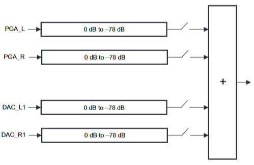
Of course, the mixing module is entirely optional. If mixing is not required in the application, the simplest approach is to directly output DAC_L3 and DAC_R3 via the audio path selection control at the Line Out interface.
HPOUT
The biggest difference between HPOUT and Line Out is that the HPOUT interface incorporates power amplification, allowing it to directly drive low-power headphones and speaker peripherals. The advantage of using this interface is that for driving low-power peripherals, no external power amplifier is required, resulting in a simpler circuit design and lower cost.
The peak-to-peak output voltage of the Audio Codec’s HPOUT interface is generally 1V–2V (with adjustable gain), matching the input requirements of headphones (typical headphone sensitivity is 90–110 dB/mW). Its output impedance is (low output impedance ensures flat frequency response without low-frequency attenuation when driving headphones), making it suitable for driving low-impedance loads (16–32 ), with a relatively high output current (30 mA)—a sharp contrast to the Line Out interface, which suits high-impedance loads and has a minuscule output current.
HPOUT is specifically designed for driving headphones, and its output power range (15–30 mW) fully matches the requirements of typical headphones (e.g., the power of a 32Ω headphone at 1 Vrms is approximately 30 mW).
The naming of HPOUT can easily cause confusion. For instance, in the TLV320AIC3101, HPOUT stands for High Power Output. However, in reality, the built-in amplifier power of the HPOUT interface is quite small, suitable only for driving headphones or very small speakers, so it can hardly be called “high power.” The term “High Power” here is relative to the Line Out interface, because Line Out lacks a built-in amplifier and has a tiny output current. In fact, if this interface is solely used to drive headphone loads, calling it “Head Phone Output” would be much more appropriate.
Once you fully understand the Line Out structure diagram above, understanding the HPOUT structure diagram becomes much easier. The DAC output, mixing module, and analog audio signal path management modules are identical to those of Line Out. The biggest difference between the two is that the HPOUT interface includes power amplification prior to the output stage (indicated by the final triangle), enabling HPOUT to drive low-power loads within its power limits.
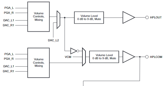
Aside from the Line Out and HPOUT interfaces mentioned above, some Audio Codecs also feature a built-in analog audio output interface with even higher output power called SPKOUT. The SPKOUT interface can drive 4–8 speakers, achieving output powers around 100–150 mW to meet the driving needs of small-power speakers. In fact, the TLV320AIC3101 combines HPOUT and SPKOUT into a comprehensive HPOUT interface that can drive both headphone loads and low-power speakers.
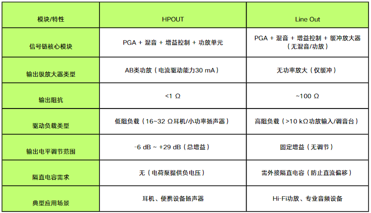
The table below summarizes the application-characteristic differences between the Line Out and HPOUT interfaces:
Introduction to Digital Audio Interfaces
In addition to supporting the analog audio input and output interfaces described above, typical Audio Codecs also provide digital audio data transmission interfaces. At a minimum, these digital transmission interfaces are used for:
- Transmitting digital audio data—obtained by AD-converting analog audio captured by microphones—via the digital audio interface to a DSP for further processing.
- Receiving digital audio data transmitted from a DSP via the digital audio interface, which is then DA-converted and played back on speakers, headphones, or other devices.
For Audio Codecs, the most commonly used digital audio interface is the I2S interface. A single I2S interface can be used to transmit dual-channel audio data containing two independent audio streams. To transmit more audio channels simultaneously using the I2S hardware interface, some Audio Codecs also support Time-Division Multiplexing (TDM) over the I2S hardware interface to transmit multi-channel audio data protocols.
I2S Interface
I2S (Inter-IC Sound) is a synchronous serial interface dedicated to audio data transmission, characterized by simplicity, high efficiency, and strong anti-interference capability. The I2S interface transmits digital audio data, typically represented in PCM (Pulse Code Modulation) format—which essentially corresponds to digital audio data converted from voice captured by microphones in the Audio Codec, or digital audio data received from a DSP that needs to be DA-converted by the Audio Codec and played back through speakers.
Parameters associated with digital audio data transmitted via I2S include the sampling rate (e.g., 16 kHz, 32 kHz, 44.1 kHz, 48 kHz, etc.), bit depth (e.g., 16-bit, 24-bit, etc.), and channel count (e.g., stereo dual-channel). During actual transmission, the I2S interface synchronizes audio data transmission using clock signals. It uses multiple clock signals to control data transmission and reception, ensuring accurate audio data transfer.
The signal lines of the I2S hardware interface include:
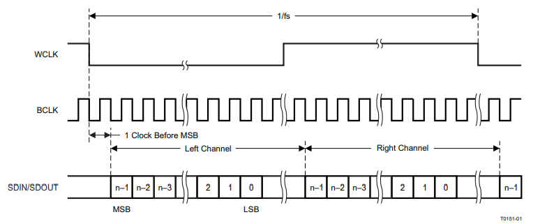
SDIN/SDOUT(Serial Data): Serial data lines used for transmitting digital audio data externally or internally.WCLK(Word Clock): Word select signal used to indicate whether the current transmission corresponds to the left or right channel data. Typically,WCLKhigh level indicates left channel data, and low level indicates right channel data.BCLK(Bit Clock): Serial bit clock line used to control the data sampling rate. Audio data is sampled on the rising or falling edge ofBCLK.
The diagram below shows the I2S working timing diagram of the TLV320AIC3101. In the I2S standard, data transmission for the MSB data bit of the next channel begins delayed by 1 clock cycle (BCLK) relative to the WCLK edge (rising or falling edge).
TDM Interface
As mentioned above, a single I2S interface can only transmit two independent audio data streams using left and right channels, forming a dual-channel stereo audio effect. However, in many scenarios (such as products featuring microphone arrays) where we want to transmit multiple independent audio streams, besides using multiple independent I2S interfaces, a TDM interface can also be used to solve this problem.
At the hardware interface level, the TDM interface shares the same set of physical pins (DOUT/DIN, SCK, WS) as the I2S interface, differing only in the data transmission protocol. The I2S mode is used to transmit dual-channel (stereo) audio data; the TDM mode is used to simultaneously transmit multi-channel (2–8 channels) audio data over the same physical interface, multiplexing the same data line through time slot division.
In audio codecs, the TDM interface can be used to transmit sample data of multiple independent audio channels over a single data line, with each channel’s data transmitted sequentially in pre-allocated time slots. During operation, the TDM interface and protocol divide the data transmission cycle into multiple time slots, with each slot assigned to an independent audio data channel. For example, if TDM supports 8 time slots, it can transmit 8 channels of audio data, with the 8 channels taking turns using their respective time slots to transmit data.
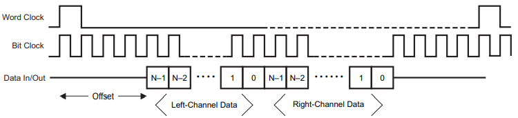
The diagram below shows the TDM data transmission timing diagram of the TLV320AIC3101. As can be seen, multi-channel audio data transmission using TDM mode utilizes the same hardware interfaces and physical pins as I2S, except that Word Clock is no longer used to distinguish left and right channels. Instead, transmission time slots for different audio streams are fixedly assigned on Data In and Data Out. Therefore, for upstream and downstream devices using the TDM interface for multi-channel audio transmission, it is necessary to negotiate and configure in advance how many audio streams are transmitted simultaneously, as well as the time slots assigned to each audio stream in the transmission timing.
When using the TDM interface, it should be noted that the TDM interface is still not fully standardized. There is a lack of unified standards regarding the details of its communication protocols (such as the number of time slots, alignment methods, and clock phases), and implementations from different manufacturers may vary to some extent. Consequently, compatibility issues may arise during the debugging and integration of upstream and downstream devices using the TDM interface, requiring the tuning of certain parameters to resolve.
PCM Interface
In addition to the I2S and TDM interfaces mentioned above, some Audio Codecs also feature a PCM interface used for transmitting digital audio signals (the TLV320AIC3101 does not have a PCM interface). This interface is mostly used in voice communication and multi-channel data transmission scenarios.
The PCM interface is generally used to transmit uncompressed multi-channel linear PCM audio data (the ability to more flexibly support multiple channels is the biggest difference between the PCM interface and I2S), supporting various scenarios such as voice and music.
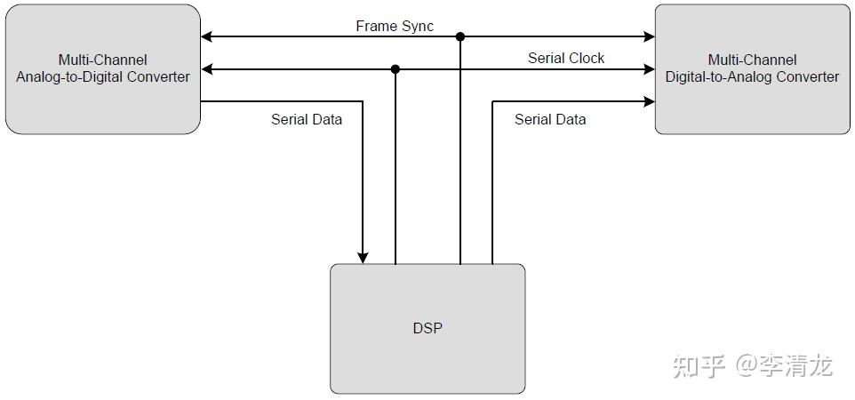
During actual use, a typical application scenario for the PCM interface is connecting with single-device multi-channel or multi-device multi-channel audio equipment, enabling the transmission of audio data across multiple independent audio channels via a single set of PCM interfaces. For example:
- A single 8-channel ADC chip connects to the Host via a PCM interface, with each time slot transmitting sample data for one channel.
- The Host connects to 4 single-channel microphones via a single PCM interface (with each device occupying 1 time slot).
From a hardware definition standpoint, the PCM interface is very similar to the I2S interface and typically includes the following data lines:
PCM_CLK(Bit Clock): Generated and controlled by the master device, with a frequency equal to . For example, at a 16-bit, 8-channel, 48 kHz sampling rate, .PCM_SYNC(Frame Sync): Generated and controlled by the master device, identifying the start position of an audio frame, with a frequency equal to the sampling rate.PCM_DIN(Data Input) andPCM_DOUT(Data Output): Transmit multi-channel audio data.
As seen from the data lines included in the PCM interface above, the definitions of PCM_CLK, PCM_DIN, and PCM_DOUT are identical to those of I2S. The main difference between the two lies in WCLK for I2S versus PCM_SYNC for PCM.
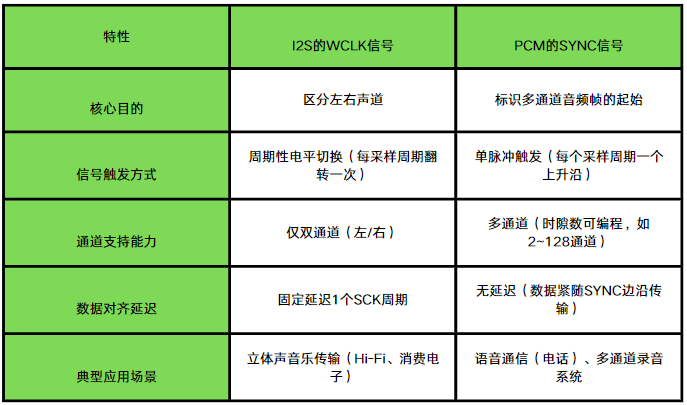
To thoroughly explain the differences between the two, one must first understand what an “audio frame” means in PCM_SYNC, which serves as the frame synchronization signal in the PCM interface.
An audio frame transmitted in the PCM interface is always initiated by a transition of PCM_SYNC (the transition edge is programmable). An audio frame contains one audio sample for each of the multiple channels connected to the PCM interface, with each audio sample occupying a fixed time slot. The time slot occupied by each channel within the audio frame is configured in the registers on both the Host and Device ends. When a PCM interface connects to multi-channel audio equipment in this manner, a single audio frame is divided into multiple time slots, each containing the audio sample data for one channel. The entire audio frame is triggered by the PCM_SYNC signal to start a complete data transmission cycle (i.e., the period of this audio frame).
As illustrated in the four-channel audio transmission diagram using a PCM interface below, a single transition of PCM_SYNC (FS) initiates the transmission of one PCM Frame. A PCM Frame contains audio sample data for four independent channels, with each channel’s sample data occupying a fixed time slot.
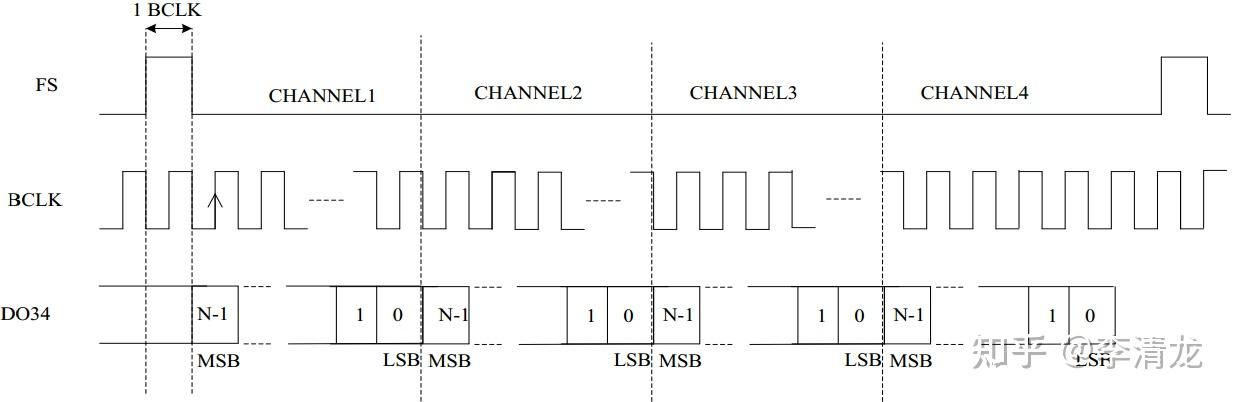
Therefore, essentially, the PCM interface also uses TDM (Time-Division Multiplexing) to transmit audio sample data across multiple channels on a single DIN and DOUT line using different time slots.
References
- TLV320AIC3101 Datasheet
- I2S/PCM - Zhihu