CMOS Sensor Exposure and Readout Timing
- 30 May, 2022
It has been a long time since I last debugged a CMOS sensor driver myself. Recently, I started working on debugging the DOL HDR mode drivers for the Sony IMX662 and IMX585 sensors. Since my understanding of CMOS operating timing had become a bit rusty, I decided to write this summary based on my recent study of various online resources.
First of all, we need to understand a very important concept for CMOS sensors: Line Time.
In simple terms, Line Time is the time it takes for the sensor to output one row of image data (including the blanking periods before and after each row) to the ISP. This duration depends on several factors, including the pixel clock (pclk), resolution (especially the number of pixel columns in the image width), the amount of horizontal blanking (H-Blank) per row, and the number of MIPI lanes, among others.
- The simplest formula to calculate Line Time is:
line_time = line_length / pclk.
Line Time is crucial because subsequent exposure times are calculated in units of Line Time, rather than absolute time units such as us or ms.
To ensure the versatility of the algorithm itself, automatic exposure (AE) algorithms typically calculate exposure times in absolute time units like us. However, to write this value into the sensor registers, it must be converted from us to Line Time.
The diagram below (from Reference 1) illustrates the pixel exposure and readout process of a CMOS sensor. The horizontal axis, , is in units of the Line Time described above, while the vertical axis represents each row of the image:
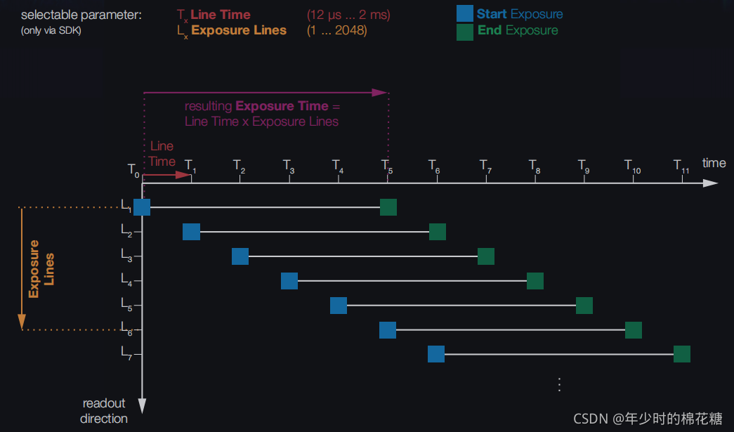
As shown, for a CMOS sensor, the start exposure time, end exposure time, and readout time slots are different for each row of pixels. However, the exposure duration (shutter speed) for each row remains identical.
- First, the first row of pixels begins exposure with an exposure duration of 5 Line Times (T0 to T5). At T5, this row begins outputting data to the ISP, which takes exactly 1 Line Time. Therefore, the first row completes its output to the ISP at T6.
- One Line Time after the first row begins exposure, the second row starts its exposure (T1). The exposure window for the second row is T1 to T6. At T6, the second row begins outputting to the ISP (just as the first row finishes its output). After 1 Line Time, it completes its output to the ISP at T7.
- The subsequent pixel rows follow this pattern sequentially.
In summary, the exposure and readout timing of a CMOS Sensor can be characterized as follows:
- The start and end times of exposure differ for each row, but the total exposure duration is identical. This ensures that the exposure level remains consistent across all rows under a stable light source.
- The exposure start time of each row is exactly one Line Time later than the preceding row, and its exposure end time is also one Line Time later than the preceding row.
- Each row outputs its data to the ISP immediately after completing its exposure, and the readout time for each row is fixed at exactly one Line Time.