Long and Short Packet Structures and the Concept of Virtual Channels in the MIPI CSI Interface
- 06 May, 2022
When transmitting data, the MIPI protocol layer communicates in units of data packets. Depending on the type of data being transmitted, these packets can be divided into two forms: long packets and short packets. Long packets are used to transmit image data, while short packets are used to transmit synchronization signals, image data format description information, and other control data.
During data communication in the MIPI protocol layer, whether transmitting long packets or short packets, the transmission always begins with an SOT (Start Of Transmission) signal and ends with an EOT (End Of Transmission) signal.
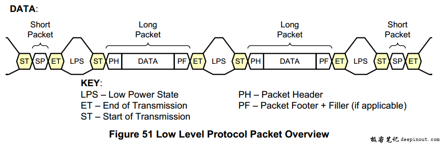
- The gap between long and short packet data transmissions is the LPS (Low Power State). During this time, MIPI enters low-power mode and does not transmit data.
Data Types of Long and Short Packets
In the packet header structures of both long and short packets transmitted over MIPI, there is a Data ID field used to define the exact type of data being transmitted in the packet.
The Data Type Subfield contained within the Data ID is 6 bits long, meaning its value ranges from 0x00 to 0x3F.
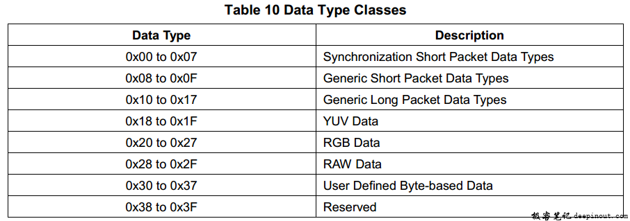
Among these data types, the most commonly used are:
-
0x00-0x07: Indicates that the short packet is used to transmit line synchronization (H-sync) and frame synchronization (V-sync) information;
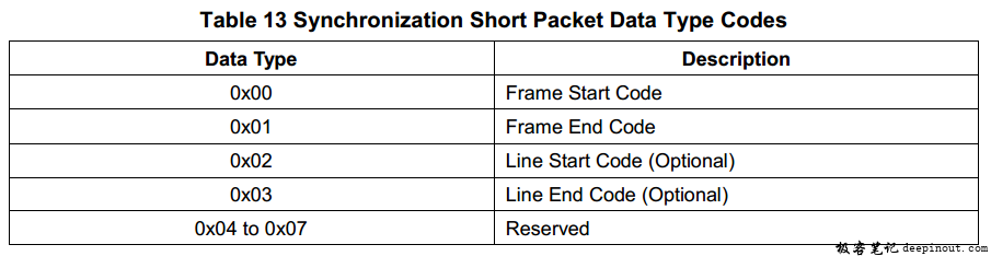
- Since a long packet typically contains a single row of image data, the aforementioned line synchronization information is optional.
-
0x18-0x1F: Indicates that the data contained in the long packet is YUV format image data, typically used for image sensors that directly output YUV data;
-
0x20-0x27: Indicates that the data contained in the long packet is RGB format image data, typically used for image sensors that directly output RGB data;
-
0x28-0x2F: Indicates that the data contained in the long packet is Bayer Raw Data format image data;
Short Packet Structure in the MIPI Protocol Layer
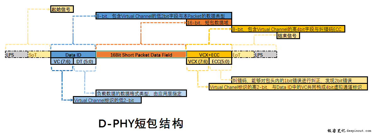
The short packet has a fixed length of four bytes:
- First is a 1-byte DATA ID:
- VC portion: bits 7:6 represent the lower 2 bits of the virtual channel (the concept of virtual channels is summarized below);
- DT portion: bits 5:0 represent the data format type of the current packet.
- Next is a 2-byte Short Packet Data field, which contains the actual data content of the short packet to be parsed by the receiver upon receipt;
- Finally, there is a 1-byte error-correction byte:
- VCX portion: bits 7:6 represent the higher 2 bits of the virtual channel;
- ECC portion: bits 5:0 are the Error Correction Code, which enables 1-bit error correction and 2-bit error detection for the preceding packet header data;
Long Packet Structure in the MIPI Protocol Layer
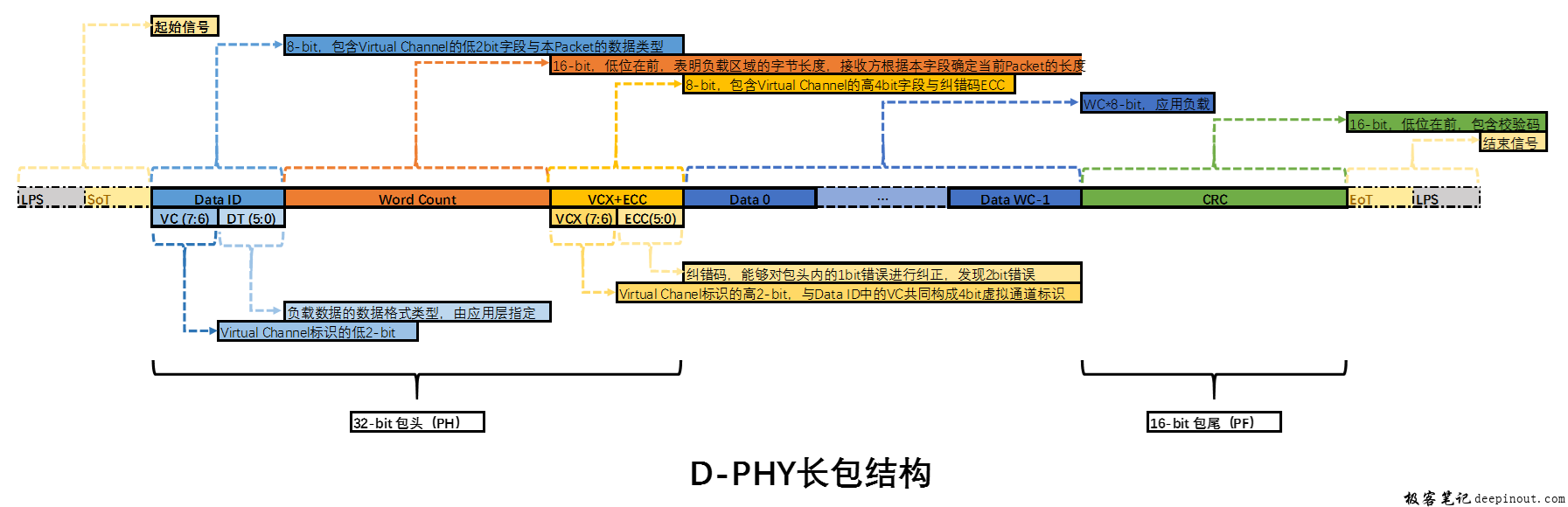
The length of a long packet is variable, with its payload size specified by the Word Count field. However, its packet header is a fixed 4 bytes:
- First is a 1-byte DATA ID, which is identical to the DATA ID defined in the short packet structure;
- Next is a 2-byte Word Count Field, indicating the byte length of the data payload;
- Then is a 1-byte packet header error-correction byte, identical to the one defined in the short packet structure;
- This is followed by the data payload, whose length is specified by the Word Count Field;
- Finally, there is a 2-byte CRC checksum field, providing a CRC value for the entire packet data.
Virtual Channels
Why is the concept of virtual channels introduced in the MIPI CSI interface?
The reason is that the MIPI CSI interface design supports transmitting multiple independent image streams simultaneously over a single MIPI interface. For example, an FPGA can be used to convert multiple image sources and transmit them to an application processor (AP) through a single set of MIPI interfaces. During simultaneous transmission, how do we differentiate between these multiple image streams? In other words, when the MIPI receiver gets a packet, how does it determine which image stream this packet belongs to?
This is where the concept of virtual channels comes into play. The so-called virtual channel is actually the Virtual Channel (VC) information contained in the packet headers of both long and short packets. For the D-PHY physical layer used by the MIPI CSI interface, up to 16 virtual channels are supported. This corresponds to 4 bits in the Packet Header, where the upper 2 bits come from the VCX field in the checksum byte, and the lower 2 bits come from the VC field in the Data ID.
In this scenario, different image streams can have different values set for the 4-bit Virtual Channel in their Packet Headers. The MIPI receiver parses this Virtual Channel to determine which image stream each received packet belongs to.
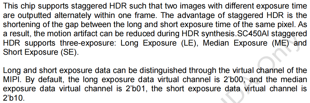
In practice, transmitting multiple independent image streams simultaneously over a single MIPI CSI interface is not very common. A more frequent use case for virtual channels is implementing High Dynamic Range (HDR) functionality in image sensors. HDR is typically achieved by exposing the image multiple times with different exposure durations (e.g., long and short exposures), sending these multi-exposure images to an Image Signal Processor (ISP) via the MIPI interface, and then merging them on the ISP to produce a high dynamic range result. Transmitting these multi-exposure images simultaneously over the MIPI interface requires using virtual channels to differentiate between the exposures, allowing the ISP to know whether each received packet belongs to a long-exposure or short-exposure frame.
Taking SmartSens’ SC450AI sensor as an example, this sensor supports Stagger HDR mode and uses MIPI Virtual Channels to differentiate between multiple exposure images: