Learning Notes on the Image Sensor MIPI CSI Interface
- 29 Apr, 2022
MIPI CSI Interface and Connection Basics
MIPI CSI is a standard interface used to transmit image data captured by an image sensor to an Application Processor (AP) or an ISP (Image Signal Processor).
The diagram below shows a typical connection block diagram between a MIPI CSI image sensor and an AP:
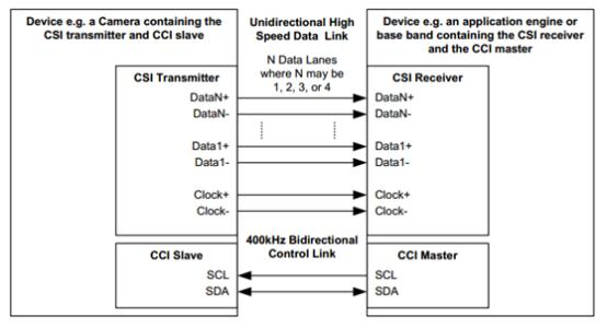
- Data between the image sensor and AP is transmitted using a CSI Transmitter and Receiver via differential serial transmission. It typically consists of one differential Clock Lane and 1, 2, 3, or 4 Data Lanes.
- No image synchronization interfaces like pixel clk, HD (Horizontal Drive/Sync), or VD (Vertical Drive/Sync) are needed between the image sensor and the AP. This control information is transmitted using short packets defined in the CSI protocol. After receiving the data, the AP parses it to extract horizontal and vertical synchronization signals.
- Image sensor register configuration is still performed through control interfaces such as I2C or SPI.
Layered Architecture of MIPI CSI
The MIPI CSI standard is defined as a layered architecture structured as follows:
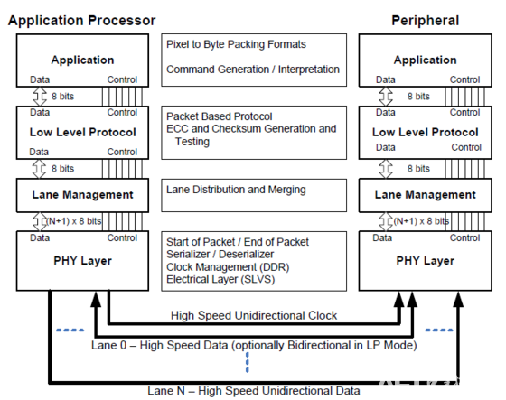
Application Layer
The Application Layer is responsible for encapsulating pixel data from the image sensor according to the protocol requirements. Because the CSI interface operates based on a byte stream, the smallest transmission unit is one byte. For data types like Raw8 and JPEG8, each pixel datum can be directly packed and transmitted. However, for non-8-bit aligned formats like Raw10, Raw12, YUV422, and RGB565, pixel data must be organized according to specific rules:
- YUV422: CB0Y0CR0 Y1 CB2Y2CR2 Y3 CB4Y4CR4 ………
- RGB565: {G[4:2], B[7:3]}, {R[7:3], G[7:5]} ………
- RGB555: {G[4:3],1’B0, B[7:3]}, {R[7:3], G[7:5]} ………
- RGB444: {G[4],2’B10, B[7:4], 1’B1}, {R[7:4], 1’B1, G[7:5]} ………
- Raw10: D0[9:2],D1[9:2],D2[9:2] D3[9:2], {D3[1:0],D2[1:0],D1[1:0] ,D0[1:0]}, D4[9:2],D5[9:2],D6[9:2],D7[9:2], D7[1:0],D6[1:0],D5[1:0] ,D4[1:0]} ……….. ………
Protocol Layer
The Protocol Layer uses a combination of long packets (used to send pixel data) and short packets (used to send commands and synchronization information) to achieve synchronous transmission of streaming data.
- Long Packet Format: A long packet consists of a 32-bit (4-byte) Packet Header, an N-byte Data Field, and a 16-bit CRC. It is essentially a TLV-like structure with a fixed-size header + variable-length data field + checksum field.
- Short Packet Format: A short packet consists of only a 32-bit (4-byte) Packet Header. Different command types in the packet header represent different command types.
- Packet Header Format: The packet header consists of an 8-bit Data Identifier (DI), a 16-bit Word Count (WC), and an 8-bit Error Correction Code (ECC).
Acronym definitions in the Protocol Layer:
- SoT: Start of Transmission; EoT: End of Transmission.
- Both short and long packet transmissions use an SoT sequence to signal the start of transmission and an EoT sequence to signal the end.
- FS: Frame Start; FE: Frame End.
- FS indicates the start of transmitting an image frame, while FE indicates the end of transmitting that frame.
- LS: Line Start; LE: Line End.
- LS indicates the start of transmitting an image line, while LE indicates the end of transmitting that line.
- PH: Packet Header; PF: Packet Footer + Filler.
- Pixel data transmitted over MIPI is encapsulated in packets; a PH sequence precedes each packet transmission, and a PF sequence follows it.
- LPS: Low Power State.
- When there is no data to transmit over MIPI, the link enters the Low Power State (LPS).
Synchronization packets like FS, FE, LS, and LE are all short packets. In contrast, pixel exposure data for the entire frame is encapsulated into packets prefixed with a PH and suffixed with a PF, transmitted over MIPI via long packets.
Individual transmission packets sent over MIPI are separated by EOT-LPS-SOT sequences.
For example, below is a transmission example for VD (Vertical Drive/Sync), i.e., frame synchronization:
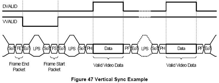
- First, an FE (Frame End) short packet indicates the end of the previous frame transmission;
- Next, an FS (Frame Start) short packet indicates the start of transmitting a new frame;
- After that, multiple pixel data long packets are transmitted to send all the pixel exposure data;
- As seen here, all short and long packets are separated by EOT-LPS-SOT sequences.
Below is a transmission example for HD (Horizontal Drive/Sync) synchronization:
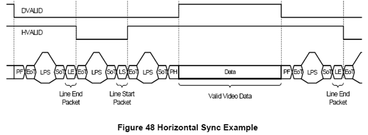
- First, an LE (Line End) short packet indicates the end of the previous line transmission;
- Next, an LS (Line Start) short packet indicates the start of transmitting a new line;
- Then comes a data long packet containing the exposure data for that line of pixel data;
- All short and long packets are separated by EOT-LPS-SOT sequences.
For the HD and VD signals essential to image sensor streaming data transmission, short packets are used:
- Frame sync short packets (FS, FE): Every frame must start with a Frame Start Packet and end with a Frame End Packet.
- Line sync short packets (LS, LE) are optional: For RGB, YUV, and RAW data formats, each long data packet must contain a full line of image data. Thus, each data long packet received by the receiver represents one line of pixel data, making LS and LE unnecessary to mark the start and end of a line.
Lane Management Layer
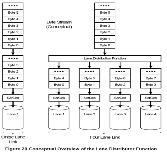
The Lane Management Layer distributes data from the Protocol Layer across different physical lanes according to the connection and configuration of the physical layer lanes, mapping to the physical interface transmission conditions. Correspondingly, the Lane Management Layer on the receiver side uses the same rules to recombine the data from multiple data lanes.
PHY Layer — D-PHY
For the physical layer of MIPI CSI, the most widely used specification currently is D-PHY. In fact, the MIPI DSI specification used for display interfaces also utilizes D-PHY, meaning the physical layer for CSI and DSI interfaces is identical.
In D-PHY, PHY stands for “Physical Layer”. But what does “D” mean? The MIPI D-PHY specification notes that the initial version was targeted at 500 Mbits/s, and “D” is the Roman numeral for 500. Similarly, “C” and “M” represent 100 and 1000 in Roman numerals, which explains the origin of the names C-PHY and M-PHY.
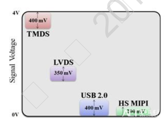
The MIPI D-PHY protocol defines two transmission modes: High-Speed (HS) mode and Low-Power (LP) mode, each using different voltage levels and transmission mechanisms. In HS mode, differential signaling is used, with signal levels ranging from 100 mV to 300 mV (200 mV swing). In LP mode, single-ended signaling is used, with signal levels ranging from 0 to 1.2 V (1.2 V swing). In HS mode, data transmission rates can reach 80 Mbps to 1 Gbps (v1.0) or 80 Mbps to 1.5 Gbps (v1.1), employing a source-synchronous transmission method where the master device provides a DDR clock to the slave device. In LP mode, the transmission rate is 10 Mbps, during which the differential pair (used in HS mode) operates as two independent single-ended signal lines. Regardless of HS or LP mode, data is transmitted LSB first and MSB last.
Since a single lane can reach a maximum transmission bandwidth of 1.5 Gbps, and the widely used CSI-2 standard supports up to 4 data lanes, a total transmission bandwidth of up to 6 Gbps can be achieved.