Sensor Flicker Issues in CMOS Image Sensors
- 26 Apr, 2022
Due to the use of a rolling shutter in CMOS image sensors, the exposure start and end times vary line by line. When operating under AC mains power supply or stroboscopic LED fill lights, a noticeable sensor flicker issue occurs:
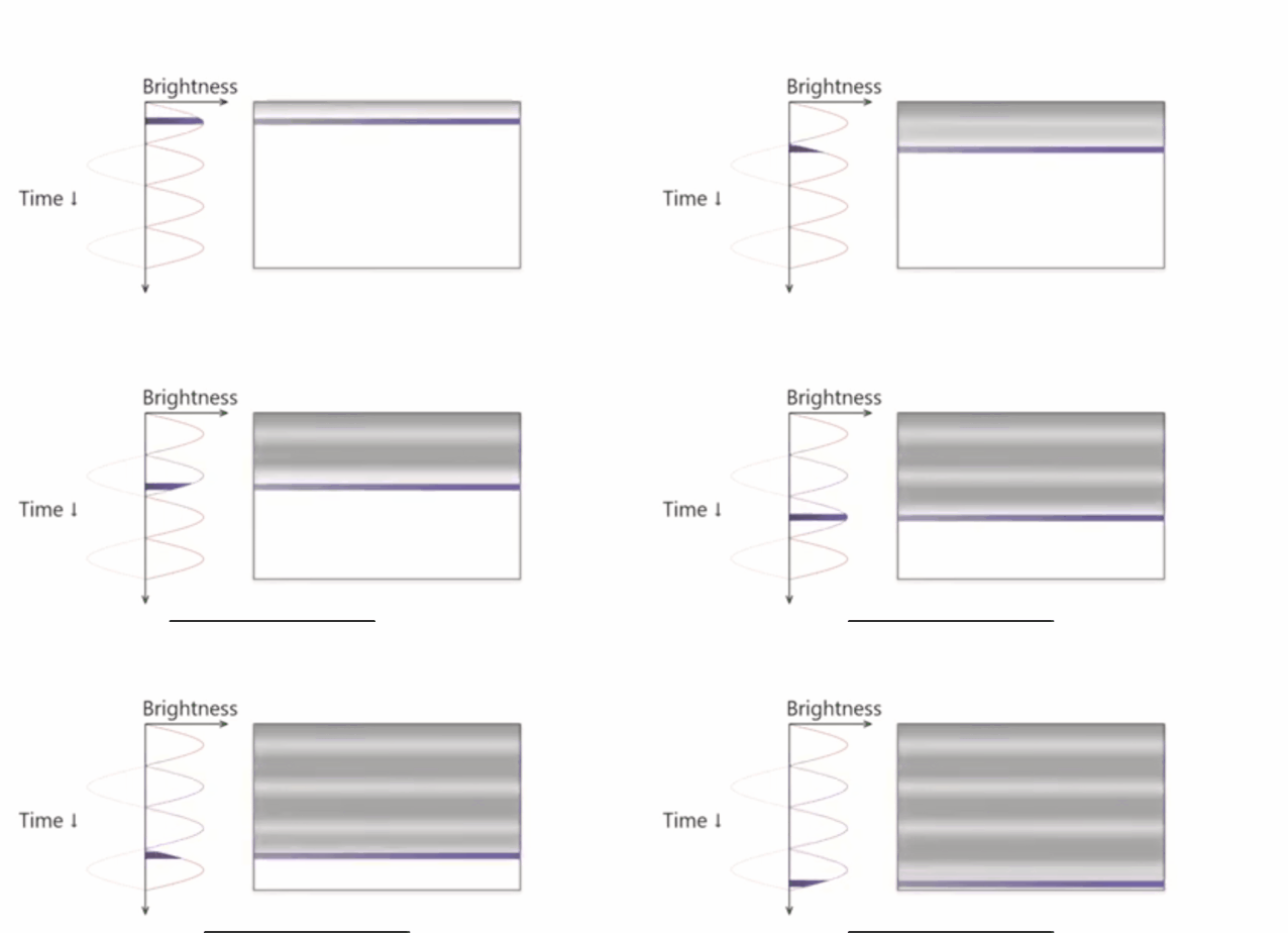
- That is to say, during sensor exposure, the exposure timing differs for every row from top to bottom. Meanwhile, the light source intensity is constantly fluctuating (taking China’s 50 Hz AC grid power as an example, the light intensity varies as a rectified sine wave at a frequency of 100 Hz). Rows exposed near the peaks of the intensity wave receive the maximum illumination and appear brightest for a given exposure time; conversely, rows exposed near the zero-crossing points receive the minimum illumination and appear darkest. The resulting full-frame exposure displays alternating bright and dark horizontal bands, as shown in the animation above.
- Fundamentally, this issue stems from the row-by-row exposure timing differences caused by the CMOS rolling shutter. If a global shutter were used, all pixel rows across the frame would start and end exposure simultaneously, resulting in uniform exposure brightness across the image and eliminating vertical bright/dark banding.
- However, under AC or stroboscopic lighting, even global shutters present another issue: if the exposure trigger time for each frame occurs at different points along the light intensity fluctuation curve, the exposure brightness will vary frame by frame. This results in noticeable video brightness flickering across frames. To resolve this, a global shutter must trigger exposure at the exact same phase location on the light intensity curve for every frame.
This behavior is dictated by the working principle of rolling shutters in CMOS sensors. However, the problem can be resolved by carefully controlling the exposure time.
Specifically, the key is to ensure that the exposure duration is an exact integer multiple of the light intensity modulation period, with the minimum exposure time equal to one light intensity period. This ensures that regardless of when any given row starts and ends its exposure, the total integration time covers a complete, integer number of light intensity variation cycles, maintaining uniform brightness across all rows.
- For a 50 Hz AC power supply, the exposure time should always be set to an integer multiple of 10 ms, with a minimum exposure time of 10 ms.
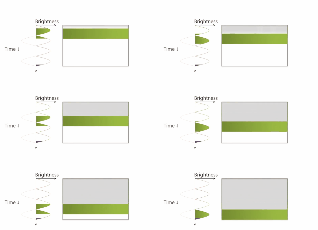
This constraint also applies to HDR imaging modes. In multi-exposure HDR capture, the shortest exposure frame must have a minimum exposure time equal to one light source modulation period, and the exposure times for the other frames must also be integer multiples of this period.