Detailed Explanation of Descriptors for USB Composite Devices and UVC Profiles
- 24 Jul, 2020
USB Composite Device
A USB composite device, as it is called, is a single USB device that incorporates multiple functions. Each function’s specific implementation includes one or more independent Interfaces, but the entire device has only one PID and VID. Multiple device functions are combined through internal logic and interface groupings to form a single external device.
USB composite devices can be categorized into two scenarios:
- Each individual function within the device uses only one Interface for its implementation
- These are known as composite devices without multi-interface functions, for example: HID Transfer + MSC, HID Transfer + HID Keyboard, and HID Mouse + HID Keyboard;
- In this case, the
bDeviceClass,bDeviceSubClass, andbDeviceProtocolparameters of the USB device’s device descriptor must be set to0x00,0x00,0x00; - The
bNumInterfacesparameter in the device’s configuration descriptor specifies the number of internal interfaces; - Subsequently, the
bInterfaceClass,bInterfaceSubclass, andbInterfaceProtocolparameters in each interface descriptor specify the type of USB class provided by that interface;
- A particular individual function within the device requires a combination of multiple Interfaces
- These are known as composite devices with multi-interface functions, for example: VCOM + HID Transfer, VCOM + MSC, VCOM + HID Keyboard, Dual VCOM, and Audio + HID Transfer.
- In this scenario, an IAD (Interface Association Descriptor) is required to group multiple interfaces of a multi-interface function together. The device descriptor’s
bDeviceClass,bDeviceSubClass, andbDeviceProtocolparameters for this USB device must then be set to0xEF,0x02,0x01.
Differences Between USB Composite Devices and USB Compound Devices:
- A USB Composite Device is a single USB device with only one PID and VID, but it contains multiple functions, which are implemented internally through separate Interfaces;
- A USB Compound Device contains an internal USB Hub and multiple USB functional devices. These devices connect to the external USB Host via the internal Hub. Each USB device has its own PID and VID, essentially acting as an independent peripheral. Therefore, a USB Compound Device includes multiple sets of PID/VIDs;
- As defined in the USB 2.0 specification:
- When multiple functions are combined with a hub in a single package, they are referred to as a compound device.
- A device that has multiple interfaces controlled independently of each other is referred to as a composite device.
IAD Descriptor
The USB IAD (Interface Association Descriptor) is used to group multiple interfaces within a USB device into a single functional unit.
- Therefore, an IAD can be seen as a grouping operation for multiple interfaces, combining them into a single group to provide a complete function externally.
For an IAD device, the bDeviceClass, bDeviceSubClass, and bDeviceProtocol parameters in the USB device’s device descriptor must be set according to the following rules for the USB Host to correctly identify and parse the IAD device’s subsequent configuration descriptor information:
bDeviceClass:0xEFbDeviceSubClass:0x02bDeviceProtocol:0x01.
The specific function or USB class indicated by the IAD descriptor is specified by the bFunctionClass, bFunctionSubClass, and bFunctionProtocol parameters within the IAD descriptor. For example, if this IAD descriptor defines a USB Video class function, the IAD descriptor’s relevant information should be set as follows:
bFunctionClass:0x0EbFunctionSubClass:0x03bFunctionProtocol:0x00
Definition of IAD Descriptor Parameters:
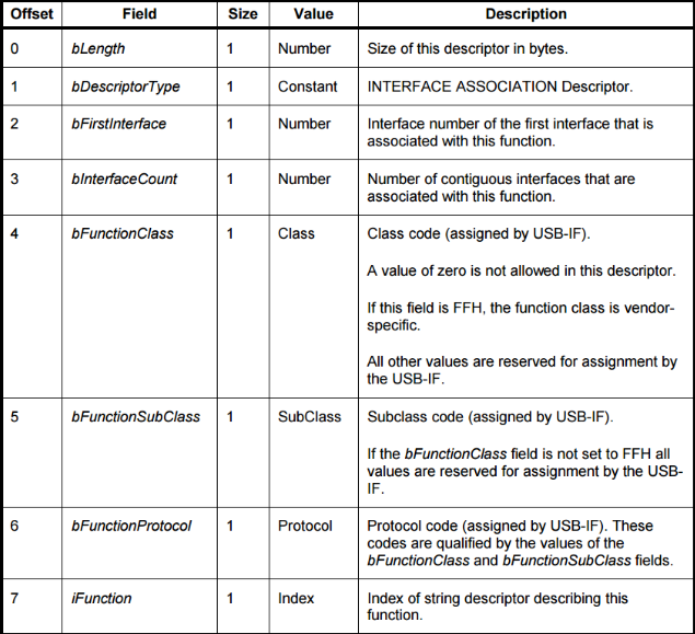
bFirstInterfaceindicates the number of the first Interface used by this IAD descriptorbInterfaceCountindicates the number of interfaces that this IAD descriptor needs to encompassbFunctionClass,bFunctionSubClass, andbFunctionProtocoldefine which USB class function this descriptor implements;
The main USB device classes defined in the USB specification that require the use of an IAD descriptor are:
- USB Video Class Specification (class code =
0x0E) - USB Audio Class Specification (class code =
0x01) - USB Bluetooth Class Specification (class code =
0xE0)
Note:
- The interface numbers specified for multiple interfaces used in an IAD descriptor must be contiguous. That is, the interface numbers within an Interface Group under this IAD must be sequential;
- A composite USB device can contain multiple IAD descriptors. It is only necessary to clearly define the interfaces occupied by an IAD function using the interface configuration information within the IAD descriptor. Additionally, each IAD descriptor must precede the multiple interface descriptors it encompasses;
UVC Device Interfaces and IAD Descriptor
All UVC devices are multi-interface devices. A UVC device should have at least two interfaces: a VideoControl (VC) Interface and a VideoStream (VS) Interface. The specification explicitly requires a device with usable, actual UVC functionality to have one VC Interface and one or more VS Interfaces.
- The VC Interface is used for configuring, controlling, and setting the UVC device into different functional states;
- The VS Interface is responsible for defining the various video stream formats supported by the UVC device, as well as the transmission of video data streams;
- Full UVC functionality relies on the cooperation between the VS Interface and the VC Interface.
Since UVC devices need to combine two interfaces (VS + VC) to provide audio and video transmission and control services, the UVC specification also explicitly requires UVC devices to use an Interface Association Descriptor (IAD) to describe this collection of Interfaces, which includes VC and VS.
- In the UVC device descriptor, the
DeviceClass,DeviceSubclass, andDeviceProtocolmust also be set for an IAD device;
Video Control Interface
Key components included in the Video Control Interface:
- Input Terminal: Describes the device’s input terminal and its supported functions;
- Output Terminal: Describes the device’s output terminal and its supported functions;
- Camera Terminal: Describes the device’s camera functions, such as Focus, Zoom, etc.;
- Selector Unit: Essentially a multiplexer component;
- Processing Unit: Describes the device’s image processing functions, such as grayscale, exposure, and brightness control;
- Extension Unit: Describes additional extended functions supported by this device; it is optional;
An example of a Video Control Interface:
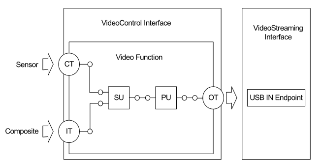
Therefore, the Video Control Interface effectively connects the various types of Terminals and Units mentioned above to form a pipeline for audio and video stream processing, ultimately providing audio and video stream data externally via the Output Terminal.
All control-type commands sent by the USB Host to the UVC camera are handled through this interface.
Video Streaming Interface
The Video Streaming Interface is specifically responsible for transmitting UVC device video data to the Host.
A UVC camera typically supports various image transmission formats with different resolutions and frame rates. All supported video formats must be defined in the Video Streaming Interface descriptor using Video Streaming Frame Type descriptors.
- Different encoding formats, resolutions, and frame rates have varying USB transmission bandwidth requirements. The main encoding formats currently supported are YUV, MJPEG, and H.264;
- To support high-definition, high-frame-rate UVC transmission, only compressed data formats like MJPEG and H.264 can be used;
Each Video Streaming Interface must include an ISO or Bulk endpoint for transmitting Video Streaming data, as well as an optional Bulk endpoint for transmitting still image data (provided that the UVC Camera has already implemented a still image capture mechanism).
An Example of a USB UVC Camera + HID Device
The reference documentation, USB Interface Association Descriptor, provides an example of a USB device that includes both UVC Camera and HID functionalities.
This device has two main functions:
- Video Class, i.e., UVC functionality
- This function is defined by an IAD descriptor, which includes a Video Control Interface (i.e., Interface 0) and a Video Streaming Interface (i.e., Interface 1);
- After the USB Host parses this IAD descriptor and its subsequent VC and VS Interface descriptors, it loads the video class driver for processing.
- HID functionality
- This function includes an Interface that implements HID functionality (i.e., Interface 2);
- After the USB Host parses the descriptor corresponding to this interface, it automatically loads the Host-side HID class driver for processing;
The USB descriptor structure for this device:
Device Descriptor
BYTE  bLength      0x12
BYTE  bDescriptorType    0x01
WORD  bcdUSB      0x0200
BYTE  bDeviceClass     0xEF
BYTE  bDeviceSubClass   0x02
BYTE  bDeviceProtocol    0x01
BYTE  bMaxPacketSize0   0x40
WORD  idVendor      0x045E
WORD  idProduct      0xFFFF
WORD  bcdDevice     0x0100
BYTE  iManufacturer     0x01
WORD  iProduct      0x02
WORD  iSerialNumber    0x02
BYTE bNumConfigurations 0x01- This indicates a multi-function composite USB device containing an IAD descriptor;
Configuration Descriptor
BYTE  bLength      0x09
BYTE  bDescriptorType    0x02
WORD  wTotalLength    0x....
BYTE  bNumInterfaces    0x03
BYTE  bConfigurationValue  0x01
BYTE  iConfiguration     0x01
BYTE  bmAttributes     0x80 (BUS Powered)
BYTE bMaxPower 0x19 (50 mA)bNumInterfacesspecifies the number of USB interfaces contained within. Here, UVC functionality includes 2 interfaces via the IAD descriptor, and HID includes one interface;
IAD Descriptor
BYTE  bLength      0x08
BYTE  bDescriptorType    0x0B
BYTE  bFirstInterface    0x00
BYTE  bInterfaceCount    0x02
BYTE  bFunctionClass    0x0E
BYTE  bFunctionSubClass   0x03
BYTE  bFunctionProtocol   0x00
BYTE iFunction 0x04bInterfaceCountindicates the number of interfaces this IAD descriptor needs to include. Here it is 2, referring to the Video Control Interface and Video Streaming Interface;bFirstInterfaceindicates the number of the first Interface used by this IAD descriptor. Here it is 0, meaning the two Interfaces used by this IAD are Interface 0 and Interface 1;- The subsequent
bFunctionClass,bFunctionSubClass, andbFunctionProtocoldefine this as a Video class function;
Video Control Interface Descriptor
BYTE  bLength      0x09
BYTE  bDescriptorType    0x04
BYTE  bInterfaceNumber   0x00    Interface number is 0
BYTE  bAlternateSetting   0x00
BYTE  bNumEndpoints    0x01    This interface uses one communication endpoint
BYTE  bInterfaceClass    0x0E
BYTE  bInterfaceSubClass   0x01
BYTE  bInterfaceProtocol   0x00
BYTE iInterface 0x05- Following this are the internal descriptor information for the Video Control Interface (i.e., the organization of various Terminals and Units within this VC Interface) and the endpoint information descriptors for this interface;
Video Streaming Interface Descriptor
BYTE  bLength      0x09
BYTE  bDescriptorType    0x04
BYTE  bInterfaceNumber   0x01    Interface number is 1
BYTE  bAlternateSetting   0x00
BYTE  bNumEndpoints    0x01    This interface uses 1 communication endpoint
BYTE  bInterfaceClass    0x0E
BYTE  bInterfaceSubClass   0x02
BYTE  bInterfaceProtocol   0x00
BYTE  iInterface      0x06
Following this are the internal descriptor information for the Video Streaming Interface (i.e., the detailed list of various Video Formats contained within this VS Interface) and the endpoint information descriptors for this interface;
HID Function Corresponding Interface Descriptor
BYTE  bLength      0x09
BYTE  bDescriptorType    0x04
BYTE  bInterfaceNumber   0x02    Corresponding Interface number is 2
BYTE  bAlternateSetting   0x00
BYTE  bNumEndpoints    0x01    This interface uses one communication endpoint
BYTE  bInterfaceClass    0x03    Indicates this is an HID device function via Interface configuration information
BYTE  bInterfaceSubClass   0x01
BYTE  bInterfaceProtocol   0x01
BYTE  iInterface      0x07
Finally, the detailed configuration information for the HID functional interface and its corresponding endpoint descriptor information;