Summary of 5G/LTE Working Modes
- 15 Jul, 2026
Power management of 5G and LTE modules is a core component in hardware design and BSP driver development. To strike a balance between responding to the network at any time and maximizing power savings, these modules typically follow 3GPP specifications combined with hardware interfaces, resulting in several tiered working modes. This article summarizes these working modes.
From high power consumption to low power consumption, 5G/LTE modules generally include the following core working modes:
- Active Mode
- Idle Mode
- Sleep Mode
- Flight Mode
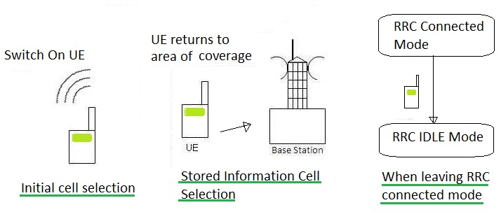
Active Mode
Active mode is the full-speed operating state of the module. When the device is making a voice call or sending/receiving network data packets (such as transmitting production test data or video streams via a socket), the module is in this mode.
In this working mode, the module’s RF transceiver is fully active, the baseband processor operates at high speed, and the module maintains a continuous RRC Connected state with the base station. This means that an exclusive signaling channel has been established between the module and the base station, and the base station has allocated dedicated physical layer resources (such as specific frequency bands and time slots) to the module. In other words, the module is not only connected to the network, but the base station has also reserved dedicated channel resources for data transmission and reception, allowing the two to interact with data at any time.
In this Active state, the specific operating status of the module’s RF link is as follows:
- RX (Receiver): Continuously active.
- TX (Transmitter): Not continuously enabled, but pulses on-demand. When there is business data to send, the module requests resources from the base station. Once approved by the base station, the TX PA (Power Amplifier) turns on instantaneously within the specified microsecond-level time slot to transmit the packet, and then immediately turns off the PA to save power. When there is no business data, the TX is basically silent; however, to maintain the RRC Connected state, the TX will still periodically turn on briefly to transmit some underlying control signaling.
For the RF link, power consumption primarily originates from the TX section. In the RRC Connected Active mode, even if there is no business data to send, as long as it does not fall back to the Idle mode, the TX will still periodically communicate with the base station. This is why the noise-floor power consumption remains at hundreds of milliamperes even when no data is being sent in the Connected state.
Additionally, in hardware specifications from module vendors such as Qualcomm, Quectel, and Fibocom, Active mode is further divided into several sub-cases: LTE Max. Power Mode, LTE Max. Throughput Mode, SA SISO Max. Power Mode, and SA Max. Throughput Mode. The core difference among these sub-modes is: whether the current power consumption bottleneck of the module lies in the RF front-end PA (Power Amplifier) or the core baseband DSP (Digital Signal Processor).
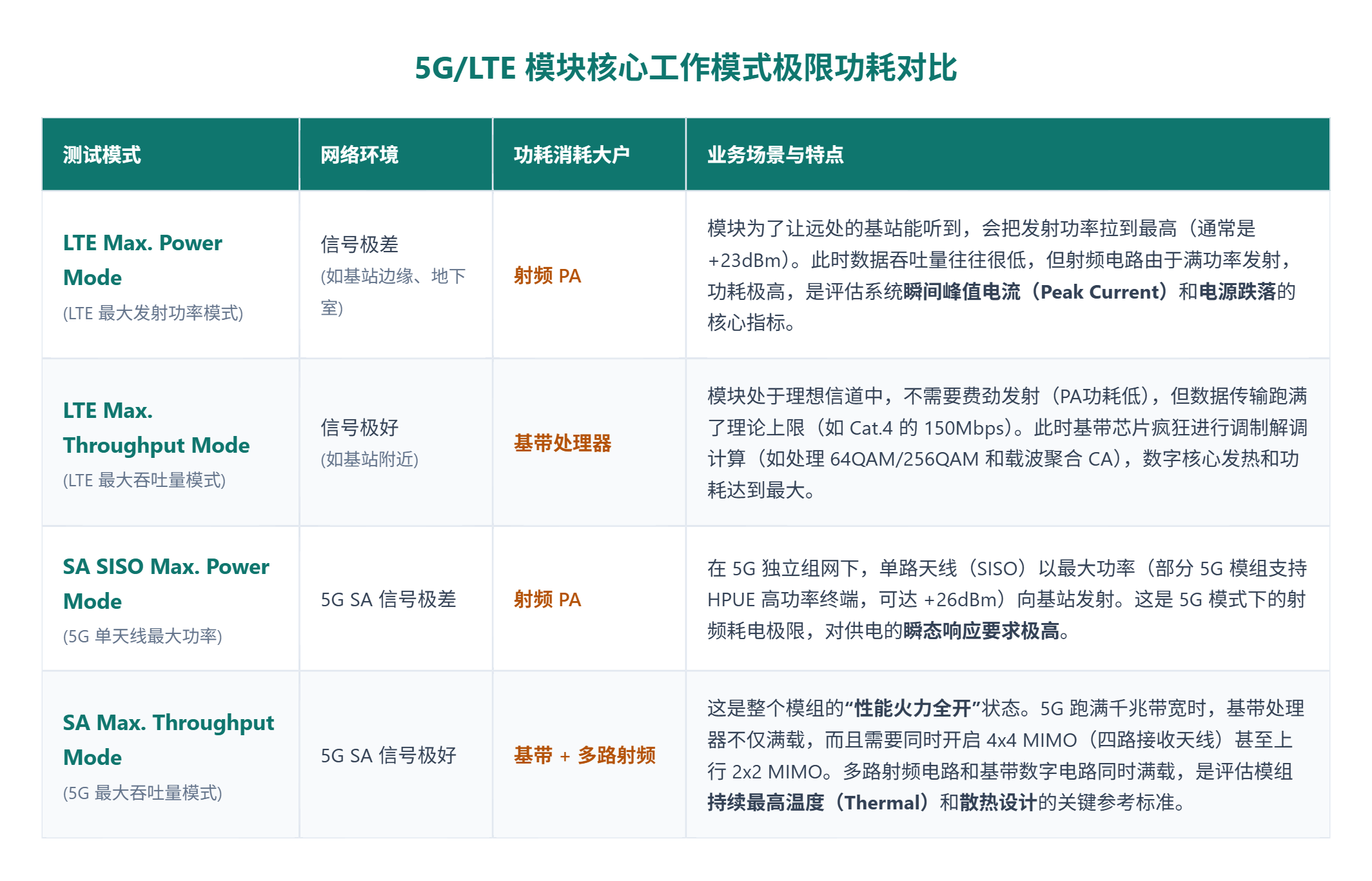
Power consumption data in these working modes is crucial when performing system hardware power evaluations and power distribution network (PDN) design: if the device is in Max Power state, the power supply must be able to withstand instantaneous large current fluctuations (e.g., requiring larger tantalum capacitors to prevent brownouts); whereas if it is in Max Throughput state, since the current remains at a relatively high average, the primary focus shifts to solving the thermal management of the board during long-term operation.
IDLE Mode
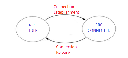
To minimize the communication power consumption of LTE/5G modules, when data transmission ends, the module releases the RRC connection with the base station and enters the IDLE state.
In the IDLE state:
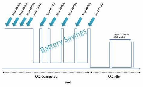
- The RF transmitter TX is completely turned off, but the receiver RX periodically and briefly turns on to listen for paging messages from the base station. This mechanism is called DRX (Discontinuous Reception). In this state, the module remains attached to the network, so it can quickly resume Active mode at any time.
- Power consumption performance in IDLE state: Moderate. Typically between tens of milliamperes (mA), depending on the DRX cycle length configured by the network (longer cycles save more power).
💡 As can be seen from this DRX workflow, this mechanism is very similar to the DTIM mechanism in Wi-Fi low-power modes.
How to Switch from Active Mode to IDLE Mode?
The decision to enter the IDLE state rests entirely with the base station (network side). The module itself cannot unilaterally disconnect and enter sleep mode; otherwise, the network will consider the module to have dropped abnormally.
The base station side typically maintains an Inactivity Timer:
- Every time data is sent or received between the module and the base station (whether uplink or downlink), this timer on the base station is cleared and reset.
- When data transmission stops, the timer starts counting. If there is no data interaction beyond the set time (usually ranging from a few seconds to over ten seconds, configured by the operator’s core network), the base station assumes the device temporarily does not need to communicate.
- At this point, the base station sends an
RRC Connection Releasemessage to the module via the control channel. Upon receiving this command, the module actively releases the physical layer resources, turns off the transmitter (TX), and officially enters the RRC IDLE state.
Furthermore, for even more extreme power savings, 3GPP introduced the RAI (Release Assistance Indication) feature in the latest low-power IoT specifications (such as NB-IoT/Cat.M). The module can attach a flag when sending the last packet of data to proactively inform the base station that communication is complete. Upon receiving this, the base station immediately issues a Release message, significantly reducing the module’s waiting time in the Active state.
DRX and eDRX
The DRX mechanism of LTE modules is essentially similar to the DTIM logic of Wi-Fi modules, allowing the module to periodically sleep and wake up to minimize RF link power consumption while maintaining a connection with the base station. Under this working mechanism, the module’s RX is turned off for most of the time (Sleep Duration), but wakes up at fixed intervals to listen to the base station’s broadcast signals to check for incoming data packets. This mechanism drastically reduces power consumption without missing pages.
In the power consumption section of LTE module datasheets, we often see conditions like DRX=64/128/256. These numbers refer to the DRX Cycle Length.
In LTE and 5G networks, the duration of 1 radio frame is fixed at 10 milliseconds (10 ms). Therefore, converting these parameters into actual physical time is very straightforward:
- DRX = 64: 64 * 10 ms = 640 ms (i.e., wakes up to listen once every 0.64 seconds)
- DRX = 128: 128 * 10 ms = 1.28 s (i.e., wakes up to listen once every 1.28 seconds)
- DRX = 256: 256 * 10 ms = 2.56 s (i.e., wakes up to listen once every 2.56 seconds)
With the explosion of IoT (such as NB-IoT, LTE Cat.M, and even Cat.1 bis), some devices (like smart water meters) only need to transmit data once a day. Waking up the RX every few hundred milliseconds or seconds is still too power-intensive. To address this issue, 3GPP introduced eDRX in the Rel-13 standard. The core of eDRX is greatly multiplied sleep time. Building upon traditional DRX, it introduces the concept of PTW (Paging Time Window). The module can sleep deeply for tens of minutes or even hours. Upon waking up, it performs traditional DRX listening a few times within the PTW window, and then enters another long period of deep sleep.
In this eDRX mode, the module and the core network negotiate the eDRX cycle length (e.g., 41 seconds, or even tens of minutes) when establishing a connection. Before the module enters sleep, the base station and the module perform a hash calculation based on the last few digits of the IMSI in the module’s SIM card to determine the time slot for each paging time window. Once the module enters sleep, the base station caches the paging messages destined for this module until that specific time slot arrives, at which point it broadcasts them via the antenna. The module similarly turns on its receiving antenna at the arrival of the same time slot to receive messages from the base station.
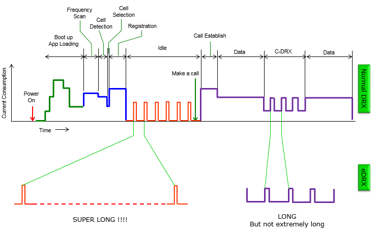
Sleep Mode
First of all, for the RF front-end, there is no difference between IDLE mode and Sleep mode. In both modes, the network-side state is RRC Idle, and the module’s RF receiver (RX) executes the exact same DRX cycle monitoring.
The fundamental difference between these two modes lies in: whether the baseband SoC (digital core) inside the LTE/5G module and the peripheral buses connected to the host processor are in a suspended state.
Consequently, power consumption influencing factors regarding sleep/wake-up involve the following aspects:
- Peripheral Interfaces and Buses: In IDLE mode, the USB bus is active at full or high speed; simply maintaining a high-speed USB connection typically consumes 10mA to 20mA of current. In Sleep mode, the USB interface enters the Suspend state, and the USB PHY is powered down or enters an ultra-low-power mode.
- Internal Main CPU of the Module: In IDLE mode, although there is no network data transmission, the module’s internal main CPU (usually an ARM core) maintains a relatively high clock frequency and operates normally (idling). In Sleep mode, the module’s operating system enters a low-level sleep state, and the main CPU scales down its frequency significantly or enters sleep.
- Internal DDR of the Module: In IDLE mode, the module’s internal DDR/LPDDR memory undergoes normal read/write refresh cycles. In Sleep mode, the memory controller enters Self-Refresh mode, retaining only a minimal baseline current to prevent data loss.
Through these power optimization measures, an LTE module in Sleep Mode can typically reduce its consumption to around 2mA to 5mA.
So, when the module is in Sleep Mode and there is a demand for data transmission, how is the module awakened? This wake-up logic can be divided into two aspects: the network side and the host side.
- Network-side Wake-up: If there is an incoming call or downlink data, the module is awakened by a base station page, and subsequently wakes up the host through a dedicated hardware pin (such as the
RIring indicator pin) or via a USB Resume interrupt. - Host-side Wake-up: If the host needs to send data, it typically pulls a dedicated GPIO (such as the
DTRpin) low/high or triggers a USB wake-up signal to rouse the module’s CPU from the Sleep state.
Flight Mode
Flight Mode is relatively straightforward. It is generally triggered via AT commands (such as AT+CFUN=4) or dedicated hardware pins (such as W_DISABLE#).
When the module is in Flight Mode, it directly cuts off the power supply to the RF circuitry, thereby disconnecting the module from the base station. However, other parts of the baseband processor (such as the SIM card interface and certain peripherals) may still be functioning, and the host can still communicate with the module via AT commands. Afterward, the module can be set back to Active mode via AT commands.