Summary of Dual-Band Wi-Fi and BT Communication Multiplexing and Concurrent Technologies
- 22 Apr, 2026
During the evolution of Wi-Fi products, Dual Band (2.4GHz and 5GHz) has become a very common and frequently used term. In communication, whether the two frequency bands are multiplexed/switched via time-sharing or can directly achieve dual-band concurrent communication forms two completely different working logics. This article attempts to explain this issue from the perspective of RF link multiplexing and concurrent processing logic.
Typical RF Communication Links
To understand the RF link multiplexing and concurrency issues of dual-band Wi-Fi and Bluetooth modules during communication, one must first have an overall understanding of the basic composition structure of an RF communication connection.
From a simplified perspective, the connection diagram of a typical RF communication link is shown below:
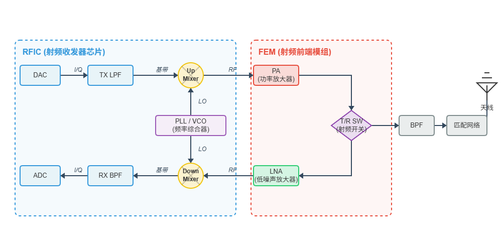
As shown in the figure above, this simplified RF communication link consists of the RFIC (also known as the Transceiver), the Radio Frequency Front-End Module (FEM), and matching circuits with antennas.
During a specific communication process (taking transmission as an example):
- The digital circuit part (the so-called digital baseband part) processes the byte stream 0/1 signals to be transmitted via radio frequency through modulation schemes such as QAM and OFDM to convert them into analog low-frequency baseband signals. This process is essentially a Digital-to-Analog Conversion (DAC) process.
- Next, the
TX LPF(Low-Pass Filter) shown in the figure filters out the high-frequency digital noise generated during DAC conversion to ensure that the analog baseband signal is smooth and pure. - The
PLL/VCO(Local Oscillator) in the figure is responsible for generating high-frequency carrier frequencies in RF communication, such as 2.4GHz and 5GHz. TheUp-Mixeris responsible for moving the analog low-frequency baseband signal to the high-frequency carrier frequency band. Therefore, after processing through this stage, the spectrum of the low-frequency baseband signal is shifted to the high-frequency carrier band, and the RF signal output from this stage is a high-frequency carrier RF signal containing the low-frequency baseband signal information. - The power of the high-frequency RF signal output from the above RFIC stage is generally relatively small, so it is further amplified in the PA of the FEM, and then coupled to the antenna for transmission after processing by the RF switch + band-pass filtering circuit + matching network.
So, among all stages in the entire RF link above, which ones can be multiplexed during communication for 2.4GHz Wi-Fi, 5GHz Wi-Fi, and 2.4GHz BT?
The main principles are as follows:
- First of all, for wireless communications in the 2.4GHz and 5GHz frequency bands, the FEM and its passive matching circuits in the figure above cannot be cross-band multiplexed due to physical frequency resonance and impedance matching characteristics. This is because the transistor matching circuits inside the PA and LNA are extremely frequency-dependent. The impedance characteristics of 2.4GHz (wavelength approx. 12.5cm) and 5GHz (wavelength approx. 6cm) differ vastly. Meanwhile, the matching network is composed of inductors (L) and capacitors (C), and its reactance $X = j\omega L + \frac{1}{j\omega C}$ is directly affected by the angular frequency $\omega$. The matching network parameters for different frequency bands need to be tuned independently. Therefore, for 2.4GHz and 5GHz RF communications, independent 2.4G and 5G FEMs and their peripheral matching circuits must be present outside the chip (or within its internal package).
- As for whether the RFIC part in the figure above can be multiplexed, it depends on the circumstances:
- Between 2.4GHz Wi-Fi and BT, despite both operating in the 2.4GHz band, because of the huge differences in baseband signal modulation methods and protocol characteristics between the two, various modules inside the RFIC (DAC, ADC, baseband filters, mixers, etc.) are almost two sets of independent physical circuits on the silicon in mainstream Wi-Fi/BT Combo chips. Otherwise, it is difficult to strike a good balance in various physical metrics.
- Whether 2.4GHz and 5GHz Wi-Fi can share an RFIC depends on whether the device communication requirement is dual-band time-division communication or dual-band concurrent communication. For time-division communication, the two can multiplex the RFIC. At this time, there is only one wideband PLL/VCO inside the chip. When switching frequency bands, the PLL jumps from locking 2.4GHz to locking 5GHz by changing the division ratio. Of course, the cost is a few milliseconds of switching lock time. For concurrent communication, the RFIC cannot be multiplexed. Two completely independent PLLs must be etched on the silicon: one firmly locks onto 2.4G and the other firmly locks onto 5G, interfering with each other not at all.
- The antenna part can be completely multiplexed. Although electromagnetic waves in the 2.4GHz and 5GHz frequency bands have different frequencies, antenna designs can utilize dual-band resonant antennas (such as PCB inverted-F antennas like PIFA, which contain two vibrators of different lengths), presenting good 50-ohm impedance at both 2.4G and 5G. In specific engineering practices, a Diplexer can be inserted after the matching network and before the antenna in the figure above. This device internally includes a low-pass filter (LPF, allowing 2.4G to pass) and a high-pass filter (HPF, allowing 5G to pass).
RF Multiplexing Design for 2.4GHz Wi-Fi and BT Combo
Based on the RF link multiplexing design principles summarized above, the following figure shows a typical RF design link for a 2.4GHz Wi-Fi and BT Combo:
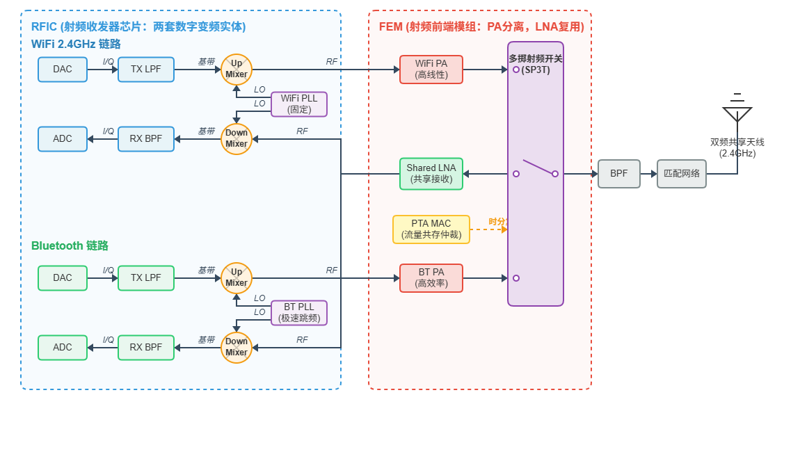
- As mentioned earlier, the baseband signal modulation specifications between Wi-Fi and Bluetooth differ significantly, and Bluetooth’s frequency-hopping communication differs greatly from Wi-Fi’s OFDM in terms of PLL requirements. Therefore, at the RFIC level, a Combo solution needs a complete and independent implementation for both Bluetooth and Wi-Fi.
- As for the FEM, 2.4GHz Wi-Fi and BT both operate in the 2.4GHz band, but because of the huge differences in modulation methods, parameters, and power during communication, they cannot directly multiplex the complete FEM module:
- LNA (Low Noise Amplifier): Since weak 2.4GHz signals enter the antenna, the system typically shares the same LNA to amplify the received over-the-air signals. After amplification by the LNA, the signal is split into two via an analog switch and sent to Wi-Fi’s Down-Mixer and BT’s Down-Mixer respectively.
- PA (Power Amplifier): Typically not multiplexed and physically separated. Allowing Bluetooth to directly use Wi-Fi’s PA for transmission would cause Bluetooth power consumption to skyrocket exponentially. Therefore, a compact and power-saving Bluetooth-dedicated small PA is usually included within the FEM.
- When the FEM shares the communication link (LNA) and antenna during Wi-Fi and BT communication, Wi-Fi transmission and Bluetooth reception cannot be performed simultaneously. At this time, a PTA (Packet Traffic Arbitration) mechanism must be used to schedule and manage the time slots used by Bluetooth and Wi-Fi.
- The antenna, matching network, and BPF parts at the RF end can be 100% fully multiplexed. This is because the frequency band is the same and the impedance characteristics are identical; Bluetooth can directly use the 50-ohm perfect matching network tuned for 2.4GHz Wi-Fi.
RF Multiplexing Design for 2.4GHz/5GHz Wi-Fi (Time-Division Multiplexing)
For most low-cost IoT devices, low-end smartphones, or single-antenna network cards, Wi-Fi chips universally adopt a dual-band selectable or time-division dual-band mechanism to support both frequency bands. Its core characteristic is: one chip with dual bands, but only one of the two can be selected at any given time. Once the Wi-Fi chip and its RF link operate in the 2.4 GHz band, the 5 GHz link remains physically powered down or dormant, and vice versa.
In terms of hardware design, to cut costs to the absolute minimum, such dual-band multiplexed chips retain only one MAC, one baseband (PHY), and one frequency synthesizer (Synthesizer/PLL) on the silicon, but the FEM parts must definitely be independent due to the different frequency bands.
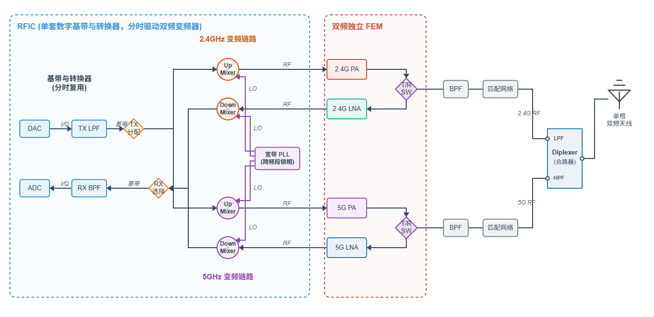
In the dual-band Wi-Fi time-division multiplexing architecture diagram shown above:
- Whether it is 2.4GHz or 5GHz Wi-Fi communication, the baseband signal modulation specifications are identical, so the baseband can be completely shared. That means there is only one set of ADC/DAC and baseband filters.
- The PLL for high-frequency signals can be multiplexed, retaining only one PLL. When communication needs to be switched between the two frequency bands, the local oscillator signal is provided by switching the phase-locked frequencies to the 2.4G and 5G mixers respectively. Of course, as mentioned above, the cost of this switching is that each switch takes a few milliseconds for the local oscillator signal to stabilize, so the switching frequency cannot be too high. However, it is sufficient for Wi-Fi communication applications that choose between 2.4GHz and 5GHz at any given moment.
- Two independent RF front-ends (FEMs) are required for the two frequency bands. In the analog high-frequency band, 2.4G and 5G must have completely independent PAs, LNAs, and T/R switches.
- Finally, the RF signals of the two frequency bands are combined using a Diplexer, and the RF signal is coupled to the same dual-band antenna for transmission.
RF Multiplexing Design for 2.4GHz/5GHz Wi-Fi (DBDC)
Next, the 2.4GHz and 5GHz Wi-Fi RF link in the Dual Frequency Dual Concurrent (DBDC) mode is relatively straightforward. The parts of the entire RF link that can be multiplexed are the fewest, and the cost is the highest:
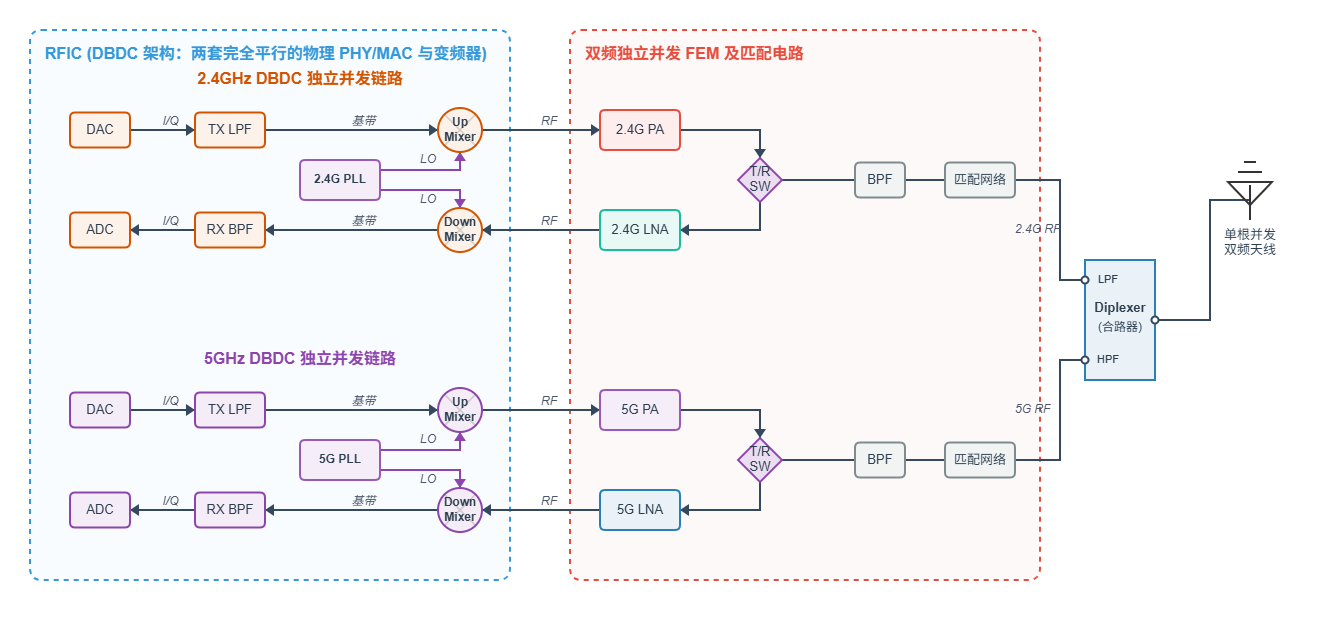
- Because of dual-band concurrency, the two frequency bands cannot multiplex the PLL. Therefore, the RFIC part consists of two complete and independent implementations.
- Due to the huge differences between the 2.4GHz and 5GHz frequency bands, the entire FEM along with its related BPF and matching circuits must also be completely independent implementations.
- Finally, the two concurrent RF paths are combined through a Diplexer and transmitted through a single antenna. Of course, they can also be transmitted using their own independent antennas.