A Detailed Summary of Gamma Correction in the Image ISP Processing Workflow
- 15 Aug, 2025
This article provides a detailed summary of the Gamma correction module in the image ISP processing workflow, explaining the reasons for including Gamma correction in ISP pipelines, as well as the core concepts and workflows used by mainstream ISPs for Gamma correction.
The Significance of Gamma Correction
In the ISP processing pipeline for RAW images output by a sensor, the Gamma correction module is a crucial image brightness non-linear transformation module. The primary purpose of the Gamma module is to bridge the gap between the linearity of the image sensor’s photosensitive response and the non-linearity of human visual perception and display devices.
Specifically, during the exposure process, an image sensor’s response to light intensity and exposure duration is largely linear. That is, if the light intensity doubles, the electrical signal output by the image sensor also doubles.
The non-linear relationship between the output voltage of a display device and its perceived brightness originates from the legacy CRT monitors. For CRT monitors, the display brightness and input voltage follow a power-law relationship of . If the linear brightness signal captured by the image sensor were fed directly into a CRT monitor for display, the resulting image would suffer from severe loss of shadow details, an overall dark appearance, compressed mid-to-high contrast, and diminished highlight gradation. Therefore, to display the linear brightness images captured by the sensor linearly on a CRT monitor, a Gamma Encode operation must be performed beforehand. This involves applying a Gamma mapping of to the sensor’s linear brightness image before sending it to the CRT monitor, allowing the CRT monitor to restore the linear brightness. The overall workflow is illustrated in the figure below:
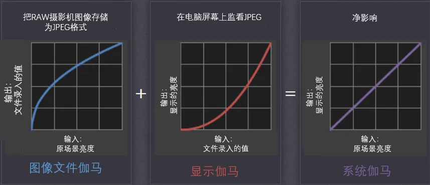
CRT monitors have long been obsolete, and current mainstream LCD/OLED displays actually feature a nearly linear brightness response. Theoretically, this would mean that raw brightness images captured by image sensors could be displayed directly on liquid crystal displays, eliminating the cumbersome Gamma mapping process described above. However, the problem is that doing so would break compatibility with the massive archive of legacy image files accumulated during the CRT era (which had Gamma Encode operations applied prior to image compression). Consequently, to maintain compatibility with historical content accumulated from the CRT era, modern LCD displays incorporate an internal correction by default. This preserves the closed-loop workflow of linear image -> encoding gamma (0.45) processing -> display gamma (2.2) -> linear image.
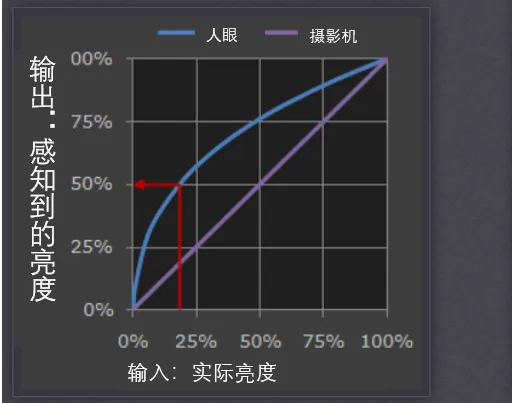
Human visual perception of light brightness is similarly non-linear, following the Weber-Fechner law. Specifically, the human eye is much more sensitive to dark areas of illumination; thus, under low-light conditions, the human eye can distinguish extremely minute changes in brightness. Conversely, it is much less sensitive to bright areas, meaning that changes in high brightness are often difficult for the human eye to perceive.
Gamma Correction Workflow
Based on the Gamma Encode processing performed on the ISP side and the automatic Gamma Decode processing performed on the display side as described above, the gamma encode executed within the ISP pipeline must process the brightness of the RGB three channels as follows:
In actual ISP engineering implementations, calculating power functions directly for every pixel is computationally expensive. Therefore, practical engineering applications utilize pre-calculated Look-Up Tables (LUTs) to achieve real-time power mapping for Gamma operations.
The input data to the Gamma correction module consists of RGB-domain data processed through Demosaic and CCM. Each pixel contains three channels (RGB). To ensure color balance across the three channels, a unified Gamma mapping table is generally applied to transform all three channels simultaneously.
- The processing method mentioned above, where three color channels share the same set of LUTs, is also known as a 1D LUT, which is essentially a Gamma brightness transformation. In some ISPs or image processing workflows, there is also the concept of a 3D LUT, where the RGB channels use independent LUT tables, typically used to implement personalized color style features.
To handle complex lighting scenarios (such as backlighting or night scenes) and better adapt to the non-linear characteristics of human visual perception, mainstream ISPs with high image quality requirements often adopt segmented programmable LUT tables to achieve finer-grained control. For instance, a segmented Gamma LUT divides the input brightness range (e.g., 0255) into three luminance intervals: shadows (020%), midtones (20%~70%), and highlights (70%~100%), and then independently configures different Gamma mapping functions for each interval:
- Shadows: Uses a low value with a gentle slope to stretch shadow details.
- Midtones: Uses a standard value to maintain natural contrast.
- Highlights: Uses a high value or logarithmic compression with a steep slope to suppress overexposure.
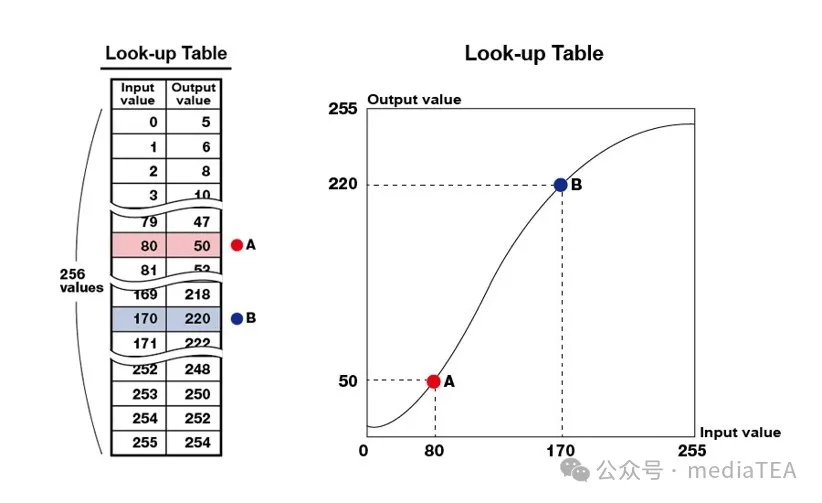
This segmented LUT design adapts exceptionally well to human visual brightness response, stretching the luminance response in shadows to preserve more detail while compressing the response range in bright areas to suppress overexposure.