Parsing SD Communication Command Protocols: CMD6
- 06 Mar, 2025
In the SD protocol, CMD6 is a relatively complex command within the interaction process between the SD host and the SD card. Its complexity is reflected in:
- The same command can be used to either read the features supported by the SD card or configure them.
- The execution of the CMD6 command and its response message read from the SD card involve communication not only on the SD CMD pin, but also data transmission on the DAT pins, whereas the execution of most other CMD commands involves only the CMD pin.
- CMD6 supports a wide range of functions, including multiple function groups, with each function group containing multiple function modes.
Therefore, based on an in-depth study of the SD Physical Layer Simplified Specification (Version 6.00), this article provides a detailed compilation of the CMD6 command interaction workflow.
A prerequisite for executing CMD6 is that the SD card must first be selected via the CMD7 command, entering the Transfer Mode.
Data Structure of CMD6 Command Interactions
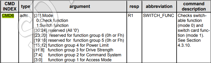
The overall data structure of the CMD6 command still adheres to the definition of CMD command data structures in [[SD Card CMD Commands and Their Response Message Data Structures]]. The CMD Command Index is 0x06, and the 32-bit Argument is structured as shown in the figure below.
- The highest bit (bit 31) is used to indicate whether the command is intended to verify if the requested configuration data is valid for the SD card, or to actually set the function mode specified by the parameters.
- Bits 30 to 24 are reserved and set to all zeros.
- Bits 23 to 0 (24 bits in total) are grouped into 4-bit sets, forming 6 function groups corresponding to the configuration parameters for each function group. In practice, only the first 4 groups are used, with groups 5 and 6 reserved for future new groups.
Within these four groups (Group 1-4), the configurable function mode values for each function correspond to the table below.
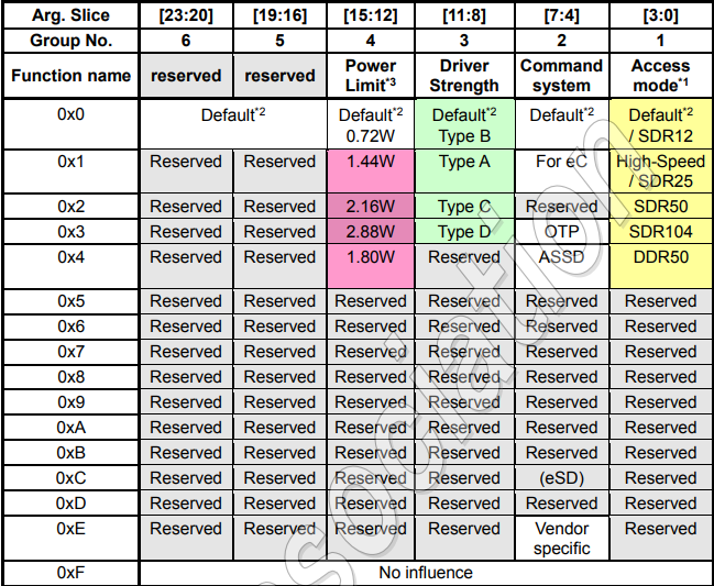
- The configuration parameters for the 4 function groups are independent of each other, each occupying 4 bits. Therefore, multiple function groups can be configured or checked simultaneously within a single CMD6 command, such as configuring both the bus speed and drive strength.
- For each function group, only one function mode can be selected at a time. Setting a function mode to
0indicates using the default value, while setting it to0xFindicates continuing to use the current value. - Function 0 of each function group is its default configuration after power-on. For example, the default SD card read/write bus clock speed (Access Mode) is SDR12, which is 25MHz.
When the SD card in Transfer Mode receives the above CMD6 message, it returns an R1 message on the CMD pin to indicate its current internal working state, and sends a 512-bit status message on the DAT data bus (for the SD card, this is a standard block read operation).
Execution Flow of the CMD6 Command
As mentioned above, the execution of the CMD6 command can be divided into two operation modes: Check (Mode 0) and Switch (Mode 1).
- The Check mode is used to check whether the SD card supports the function mode specified in the CMD6 Argument.
- The Switch mode is used to apply the function mode specified in the CMD6 Argument to the SD card.
CMD6 Check Operation
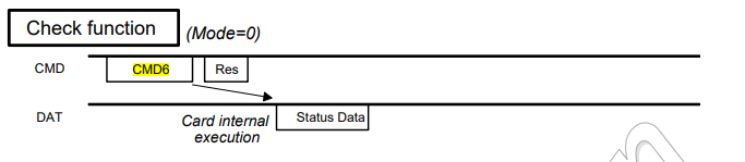
For the SD host, in the CMD6 Argument configuration, bit 31 is set to 0 to indicate that the command is a check operation. The function modes to be queried are set in their respective function groups, and this command is used to query whether the SD card supports the specified function modes.
When the SD card receives the above CMD6 command, it returns an R1 response message on the CMD pin to reply with its current working state, and then outputs a 512-bit information structure on the DAT bus. This structure contains information on whether the SD card supports the specified function modes (located between bit 399 and bit 376 of the 512-bit information structure). If supported, the index of the function mode is returned; if not supported, 0xF is returned.
CMD6 Switch Operation
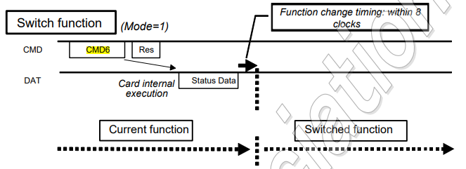
For the Switch operation of the SD host, it is similar to the Check operation described above. In the CMD6 Argument configuration, bit 31 is set to 1 to indicate that the command is a switch operation. The target function modes are then set in their respective function groups to configure the SD card with the specified function modes.
When the SD card receives the above CMD6 command, it returns an R1 response message on the CMD pin to reply with its current working state, and then outputs a 512-bit information structure on the DAT bus. This structure contains information on whether the SD card supports the specified function modes (located between bit 399 and bit 376 of the 512-bit information structure). If supported, the index of the function mode is returned; if not supported, 0xF is returned. Furthermore, 8 clock cycles after this 512-bit information structure is sent, the CLK and DAT bus operation timings switch to the working mode configured by the function mode.