SD Card CMD Commands and Response Message Data Structures
- 02 Mar, 2025
As is well known, there is a dedicated CMD pin on the SD interface between an SD card and its controller. Working in conjunction with the CLK pin, the CMD pin handles the transmission of control and configuration commands between the SD card and its host controller. During each command-mode communication, the SD host sends a CMD command structure to the card via the CMD pin, and the SD card returns a corresponding response message Rx based on the specific CMD command.
- Of course, for a few commands such as CMD6 and CMD16, besides the response message given by the SD card on the CMD pin, there will also be some communication activity on the DAT bus.
CMD Command Structure
All SD card commands in Native mode (i.e., non-SPI mode) adopt the same 48-bit (6-byte) fixed-length transmission structure:

- Start Bit: Fixed to 0 (low level), occupying 1 CLK cycle.
- Command Index: Occupies a 6-bit binary value used to define the command type (e.g., CMD0=0x00, CMD8=0x08), with an encoding range between 0 and 63.
- Argument: Fixed at 32 bits of CMD arguments. During transmission, the MSB (bit 31) is transmitted first. The argument structures vary significantly among different commands.
- CRC7 Checksum: A 7-bit Cyclic Redundancy Check code, where the CRC calculation covers the command index and argument fields.
- End Bit: Fixed to 1 (high level), occupying 1 CLK cycle.
Response Message Rx
When the SD card receives the above CMD instruction, it transmits different response messages back to the SD host via the same CMD pin in synchronization with CLK transitions, depending on the preceding CMD.
- All command responses from the SD card to the host are transmitted via the CMD pin using unidirectional serial communication.
- All responses start with a Start Bit (0) and end with an End Bit (1), which is similar to the structure of CMD commands.
- In terms of timing, the transmission of response data is synchronized by the CLK signal controlled by the host, with sampling occurring on the falling edge of CLK.
- During communication between the SD card and the host, for various CMD commands, the response messages sent back by the SD card are primarily R1, R1b, R2, R3, R6, and R7. The data structures of each response message will be explained in subsequent initialization procedures.
R1: Standard Response Message
The figure below shows the data structure of the R1 response message. The entire response message length is 48 bits, where the Command Index must match the CMD Index of the preceding CMD command in this response message, while the Card Index section contains a 32-bit internal SD card status, which is maintained internally by the SD card.

R1b: Standard Response Message with Busy Bit
The message structure of R1b is identical to R1, except that certain CMD commands require the SD card to respond with an R1 message while simultaneously providing a busy bit on the DAT0 pin. For example, in CMD12, after the SD card receives this command and enters a busy state while executing the operation, it pulls DAT0 low to provide this busy status information to the host.
R2: CID and CSD Registers
When the SD card receives CMD2 and CMD10, it returns the CID register via this response message; when the SD card receives CMD9, it returns the CSD register via this response message. The figure below shows the data structure of the R2 message:

- Note that the total length of R2 is 136 bits. Only bits 127 to 1 of the CID and CSD are included in the R2 message, and the final bit 0 is replaced by the final end bit 1.
R3: OCR Register
The length of the R3 response message is a fixed 48 bits, used to respond to the ACMD41 command and return the value of the SD card’s OCR register to the SD host.

R6: RCA Address Response
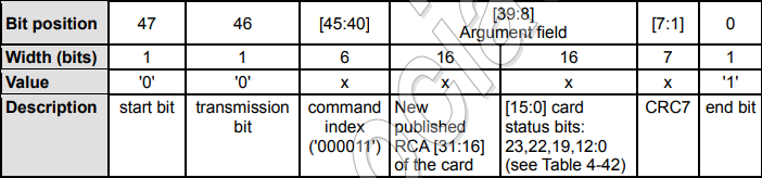
The R6 response message has a fixed length of 48 bits and is used to respond to CMD3. The upper 16 bits of the argument are the RCA address generated by the SD card itself, and the lower 16 bits are the current partial status bits of the SD card.
R7: Card Interface Status
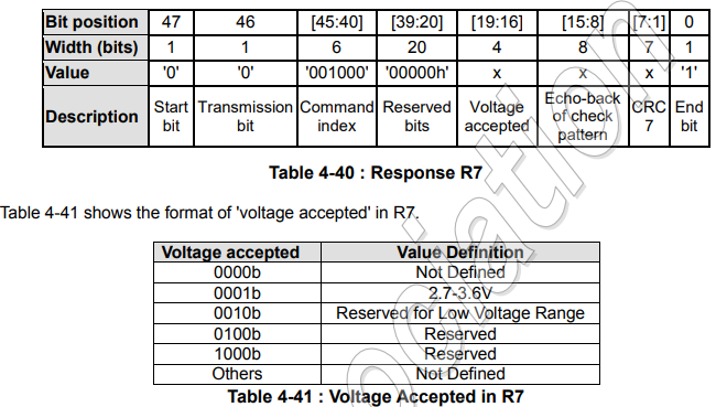
R7 is essentially returned to the SD host when the card receives CMD8, indicating the voltage range supported by the card. The length of the R7 response message is fixed at 48 bits, with the most important part being the four Voltage Accepted bits between bit 19 and bit 16.
ACMD
In command communication between the SD card and the SD host, besides the aforementioned CMD commands and response messages, there are also ACMD commands. The so-called ACMD command stands for Application CMD. The reasons for adding ACMD to the SD protocol are mainly:
- The CMD Index in the CMD structure is only 6 bits in total, which limits the number of supported commands. This ACMD mode allows for the extension of command functions under the current command data structure constraints.
- It layers the SD commands, where CMD handles hardware-related operations and ACMD handles application-level functions.
Regarding the specific ACMD communication process, each ACMD communication requires issuing a CMD55 instruction first to request the SD card to enter application mode. The SD card returns an R1 response message, in which the APP_CMD status indicates that it is in a state waiting to receive an ACMD command. The SD host then sends the ACMD command. Upon receiving it, the SD card returns the corresponding response message required by the ACMD command. The communication process for each ACMD command is shown below:
participant SD主控
    participant SD卡
    主控->>SD卡: CMD55 (声明即将发ACMD,要求SD卡进入应用模式)
    SD卡-->>主控: 通过R1消息应答,确认进入应用模式
    主控->>SD卡: ACMDX(主控继续发送ACMD命令)
    SD卡-->>主控: 执行ACMD命令所指定的扩展操作,返回响应
After the host sends the ACMD command, the response message read from the SD card is also one of the R1–R7 messages summarized above.