Summary of SD Card Classifications and Specifications
- 21 Feb, 2025
Summary of Basic SD Card Specifications
Size Types
- SD: 32×24×2.1mm (full size), largely obsolete and rarely used today
- microSD: 11×15×1.0mm, currently the mainstream application format
Pin Contact Differences:
- UHS-I and earlier: 9 pins (VCC, two VSS, CLK, CMD, DAT3-DAT0), still the mainstream application format today
- UHS-II/UHS-III: 17 pins (added differential pairs)
- SD Express: Retains legacy pins + implicit PCIe lane design
Voltage Compatibility
- Standard SD cards: Supports 3.3V only
- UHS cards: Supports dual 3.3V/1.8V voltage (requires master controller matching and mutual negotiation for voltage switching)
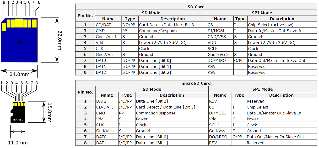
- As shown, in addition to the standard SD mode, SD cards also support SPI Mode. In this case, the data lines are reduced from four in SD mode (DAT3-DAT0) to a single data line.
SD Card Classifications
The current standard system for SD cards is quite complex, involving multiple dimensions such as storage capacity, bus protocols, and speed classes. Consequently, there are multiple dimensions of SD card classification rules.
Classification Based on Capacity
From the perspective of storage capacity, SD cards are divided into the following four categories, each defined in different SD specifications. It is worth noting that because the FAT32 file system has relatively small limits on supported file system size and single file size, SDXC cards adopt the exFAT file system by default.
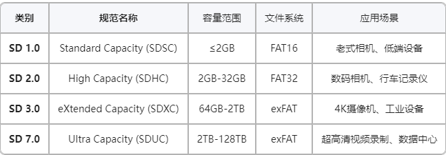
- The current mainstream applications are SDHC and SDXC. SDSC has been phased out due to its excessively small capacity.
- In fact, whether for developers or users, it is only necessary to focus on the storage capacity required by the product application, rather than which specific capacity category it belongs to.
Classification Based on Bus Interface and Bus Speed
From the perspective of the system bus interface connected to the SD card and the bus read/write speed, SD cards can be classified as follows. For developers, it is essential to pay attention to the SD interface specification of the master control chip, which dictates the clock, voltage, pin distribution, and other parameters of the SDIO interface.
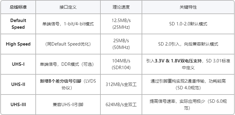
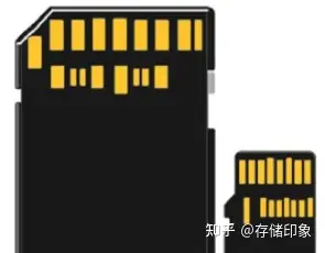
Regarding the pin structure of SD cards, UHS-I and earlier SD card specifications use the traditional 9 pins: CLK, CMD, DAT3-DAT0 (where DAT3 is also used as the CD pin for card detection), VCC, and two VSS. Starting from UHS-II, two sets of LVDS differential pairs (totaling 8 pins) are added based on the traditional SD card interface specification, bringing the total number of interfaces for the new UHS-II/III interface and card to 17. However, when a new UHS-II/III card is inserted into an older SD card slot, the newly added differential pins have no electrical connection, and the read/write access to the SD card automatically falls back to UHS-I mode or lower. This is somewhat similar to how the USB Type-C interface maintains backward compatibility with previous USB 2.0 interfaces. The figure below illustrates the pin structure of UHS-II/III cards:
Regarding the voltage supported by SD cards, in SD 2.0 and earlier specifications, the SD interface host and SD card only support a single 3.3V voltage mode and do not support dynamic voltage switching. However, starting from SD 3.0 (UHS-I), both the SD host interface and the SD card must support dual 3.3V and 1.8V voltage modes; otherwise, they cannot pass UHS certification. Under dual-voltage support conditions, the host first provides 3.3V power upon initial startup of the SD card, then exchanges dual-voltage support capabilities between both parties via the protocol sequence of CMD8 + ACMD41 + CMD11, and decides whether to switch the voltage to 1.8V based on the exchanged information.
Regarding communication modes: single-ended SDR and dual-ended DDR. In specifications prior to UHS-I, SD cards only supported single-ended SDR communication. The UHS-I specification introduced an optional DDR mode, which supports sending data twice per clock cycle, thereby doubling the data transmission rate under the same clock cycle. For UHS-I, the specification supports modes such as SDR12, SDR25, SDR50, SDR104, and DDR50. The first four are single-ended SDR modes, which simply elevate the clock frequency further based on previous SD specifications—reaching up to 208MHz and thus delivering a theoretical bandwidth of up to 104MB/s. DDR50, on the other hand, uses dual-edge triggering to transmit data, supporting a maximum clock of 50MHz in DDR mode and providing a theoretical bandwidth of up to 50MB/s. Of course, whether high-spec clock speeds and DDR mode under UHS-I can be supported requires negotiation between the master SD controller and the SD card; they can only be utilized if both parties support them.
SD 2.0 High Speed and UHS-I single-ended SDR remain the mainstream in most consumer product applications.
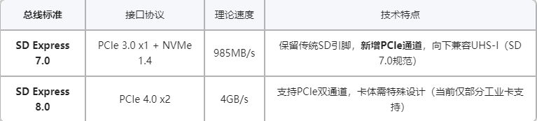
In addition to the aforementioned bus interfaces based on traditional SD interfaces, SD Express bus interfaces based on the PCIe bus communication specification have also emerged. However, SD cards and master controllers utilizing this interface are still relatively rare in product development:
Classification Based on SD Card Read/Write Speed
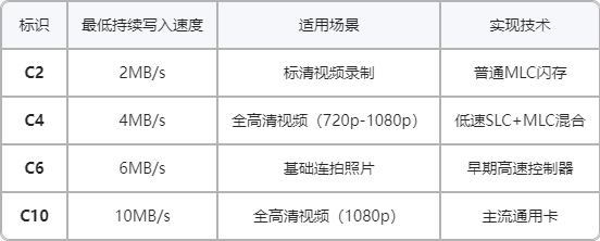
Compared to the previously discussed SD interface speeds, the classification and grading of SD read and write speeds are much more complex. First is the basic speed class starting with the letter C:
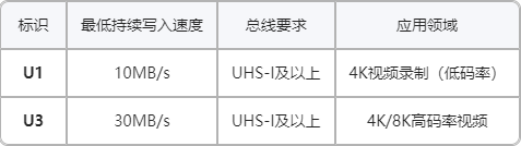
Next is the UHS Speed Class. Similar to the C-class, it primarily focuses on the write speed for large blocks of data. Since it uses the same evaluation criteria, why not continue using C?
There is also the V Speed Class specifically tailored for video file writing applications. How does it differ from the C/U speed classes?
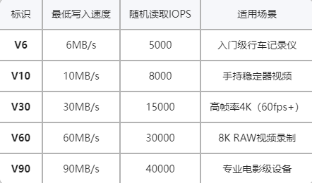
Finally, there is the A Speed Class designed for random access performance in mobile phone app applications:
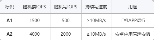
Regardless, for developers building products with SD cards, the primary focus should be on the specification version of their master SD controller, implementing specific circuits and drivers/functions according to that specification, without needing to worry too much about these various SD card speed classes. For general users, however, it is necessary to choose an SD card speed class that matches their application requirements. Naturally, to achieve optimal performance, the selected SD card speed class must also be compatible with the SD card specification supported by the master controller.
Examples of Capacity, Interface, and Speed Class Classifications
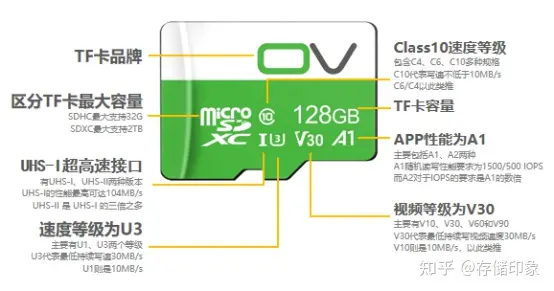
The figure below illustrates the actual markings on an SD card provided in Reference Document 1. Combined with the theoretical knowledge above, it should be quite easy to understand:
Evolution of SD Card Standard Specification Versions
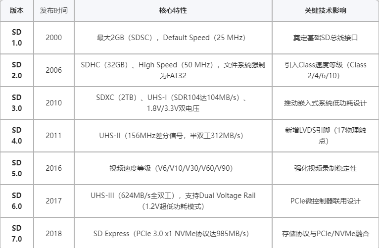
Below are the release dates of protocol specifications for major SD card versions, along with the key new features introduced in each version. Combining this with the explanations of different SD card classification standards above will make it easier to understand.