Working Principles and Application Summary of G-Sensor
- 09 Jan, 2025
G-Sensor: Gravity Sensor or Accelerometer. Its primary function is to detect sudden changes in an object’s acceleration during motion. The most typical application of a G-Sensor is in dash cams. When the G-Sensor detects instantaneous acceleration, collision, or deceleration (such as sudden braking), it automatically triggers the internal recording event of the dash cam’s camera, saving an emergency recording file as evidence for subsequent accident analysis.
Working Principle of G-Sensor
The working principle of a G-Sensor can be understood with the help of the diagram below. A mass block is fixed using two springs. When there is no acceleration, the mass block rests in the middle of the two springs. When the entire testing mechanism accelerates to the left or decelerates to the right, the mass block shifts to the right due to inertia. Based on this dynamic displacement, the magnitude of the acceleration to the right can be obtained. Conversely, when the entire testing mechanism accelerates to the right or decelerates to the left, the mass block shifts to the left due to inertia, and the magnitude of the acceleration to the left can be obtained accordingly.
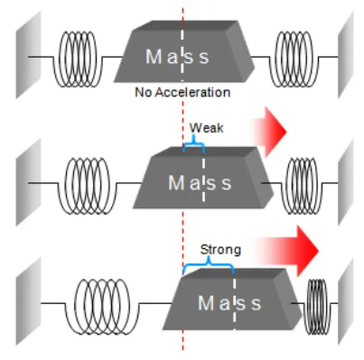
This displacement direction and magnitude correspond to the acceleration value along this axis, which is reflected in the G-Sensor as acceleration values across the X, Y, and Z axes.
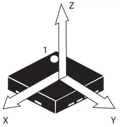
The unit of measurement for G-Sensor output values is $g$, where $1g$ represents one gravitational acceleration, which is $9.8\text{ m/s}^2$ ($1g = 1000\text{ mg}$). For G-Sensor devices, the input values are typically digital signals via I2C or SPI interfaces. Taking the STK8327 as an example, its output range is user-configurable to $\pm 2g / \pm 4g / \pm 8g / \pm 16g$. Each sampling of an axis generates 16 bits of data, and sampling all three axes once generates 6 bytes of acceleration data; these 6 bytes constitute a frame. The access to acceleration data within the G-Sensor’s internal FIFO, as well as reading acceleration data from the MCU via I2C/SPI, should be performed in units of frames.
Built-in Detection Algorithms of G-Sensors
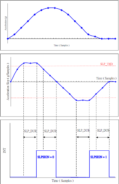
In addition to detecting, buffering, and outputting acceleration data, most G-Sensor models also have built-in common detection algorithms based on acceleration data. You can configure the enablement of these algorithms through registers and notify the MCU of detected events via external interrupts or other methods. These common acceleration detection algorithms include: motion detection, free-fall detection, orientation detection, tap detection, etc. Here is a brief introduction to two commonly used built-in G-Sensor algorithms: Any-Motion (Slope) Detection and Significant Motion. Both algorithms are available in some G-Sensors, though naming conventions may vary. Any-Motion (Slope) Detection: This algorithm is mainly used to detect and evaluate regular motion behaviors, with the addition of some filtering. The following screenshot illustrates how the Slope Detection algorithm works. The top chart shows the values of consecutive G-Sensor sampling points, the middle chart shows the comparison between individual sampling point data and the threshold, and the bottom chart shows the waveform of the interrupt pin. As seen in the figure, the interrupt pin triggers only when the amplitudes of three consecutive G-Sensor sample values exceed the set threshold, and the interrupt pin pulls low when the amplitudes of three consecutive sample values fall below the set threshold. This method filters motion event decisions to a certain extent, preventing sudden 1–2 glitches from causing false triggers on the interrupt pin, thereby making the motion detection results more stable.
The Significant Motion algorithm is mainly designed for accurate judgment of device/user position changes while avoiding excessive false triggers. The most typical application of this algorithm is in wearable devices such as smart bands and smart watches, where it can steadily detect human walking states while automatically filtering out minor acceleration change behaviors. For example, if a phone or smart band is placed on a desk, minor vibrations in the surrounding environment should be automatically filtered out. The working principle of the Significant Motion algorithm essentially involves evaluating the real-time collected data of the G-Sensor over a period of time, combining thresholds of different sizes to determine whether it is a true Significant Motion or merely minor interference.
Does the G-Sensor Still Collect Data During Sleep?
An interesting question in G-Sensor applications is: when the G-Sensor is in a sleep state, does it still need to continuously collect acceleration data?
- If yes, then there is no fundamental difference from not sleeping, and its internal acquisition circuit must remain in a working state all the time. How can low power consumption be achieved then? As we know, low power consumption is extremely important for products like smart bands and watches.
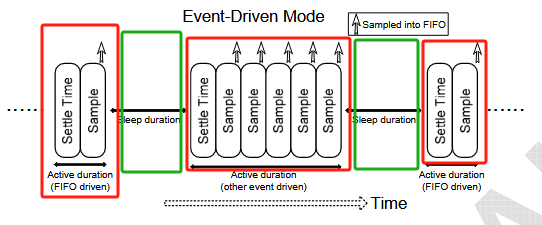
- If no, when does it wake up? The simplest answer is that it wakes up when the acceleration value exceeds a certain threshold. But the problem is, if it isn’t collecting data, how can it know whether the current acceleration value exceeds the set threshold? This turns into a “chicken-and-egg” problem. Through studying several G-Sensor datasheets, I have roughly figured out the working logic of how G-Sensors achieve low-power states: roughly speaking, even when a G-Sensor is in a low-power working mode, it still needs to wake up periodically to collect data. Its running time is divided into a sleep period and a wake-up period. During the sleep period, most circuits and data acquisition/conversion functions are turned off, maintaining extremely low operating power consumption. When the sleep period expires, the G-Sensor automatically enters the wake-up period. After waking up and passing a short stabilization time (settle time), it collects a set of data, saves it in the FIFO, and compares this set of collected data with the threshold set in the registers to determine whether the MCU needs to be woken up via an interrupt pin. If it is below the threshold, it re-enters the sleep period, waiting for the arrival of the next wake-up period. For example, the figure below shows the working timing diagram of the STK8327 in the EDM low-power mode, where the red portion represents the wake-up period and the green portion represents the sleep period.
G-Sensor Applications
Below, Sensortek’s STK8327 is used to explain the precautions for applying G-Sensors in actual products. G-Sensors from other manufacturers are largely similar in specific use cases. The STK8327 is an XYZ 3-axis accelerometer with the following main specifications:
- Supports user-configurable acceleration detection ranges of $\pm 2g / \pm 4g / \pm 8g / \pm 16g$
- Outputs acceleration values in a 16-bit digital format
- User-configurable output of 14–2000 acceleration samples per second; on-chip FIFO supports caching 32 sets of acceleration sample values
- Two interrupt pins that can be flexibly configured via registers to correspond to different internal interrupt modes
- Supported digital communication interfaces are I2C or 3-wire/4-wire SPI
- Package is $2.0\text{ mm} \times 2.0\text{ mm} \times 1.0\text{ mm}$ LGA.
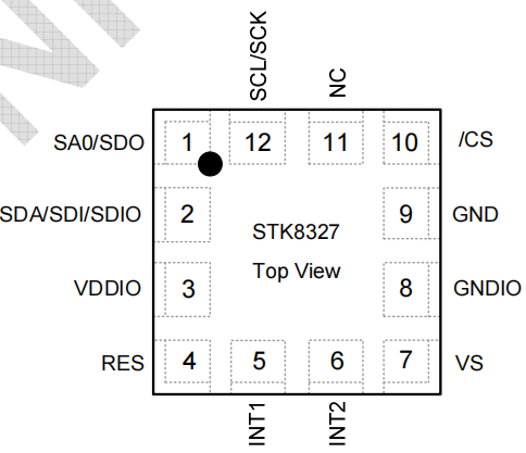
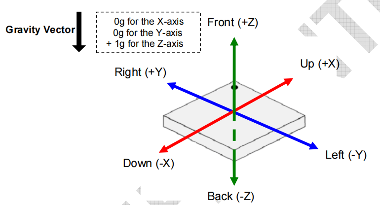
With 12 pins—excluding NC and Reserved—the remaining 10 pins are power, ground, SPI/I2C, and two interrupt pins, making it very simple to use. During layout, pay attention to the dot on the chip package; in actual use, the direction of the G-Sensor’s XYZ axes must be determined based on this dot.
Working Modes and Switching
The STK8327 has four working modes:
- Power OFF is the shutdown mode;
- Normal is the normal working mode, where the MCU can continuously use I2C or SPI to read acceleration data from the G-Sensor in Normal mode, though it is not recommended to modify registers in Normal mode;
- Suspend mode is a working mode specifically used for setting registers. In this mode, all analog circuits and crystal oscillators inside the chip stop working. Internal registers of the STK8327 can generally be configured in this mode, and after configuration, it switches back to Normal mode to read acceleration data;
- Low Power mode is a sleep working mode designed for low power consumption. In this mode, most analog circuits except the crystal oscillator are turned off, effectively reducing the operating power consumption of the G-Sensor. ![[1736848751069.png]]
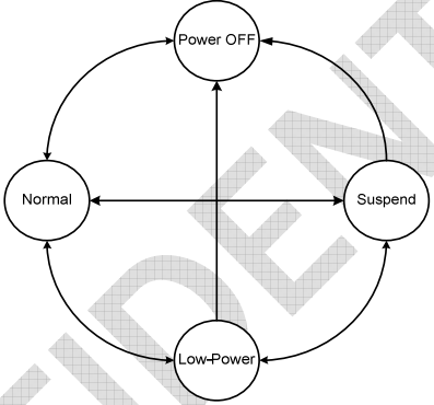
Among the four working modes, the other three are relatively simple to apply. However, Low Power is actually the core essence of G-Sensor applications, since the vast majority of products using G-Sensors rely on their Low Power mode to achieve low power consumption and motion event detection effects.
Low Power Mode
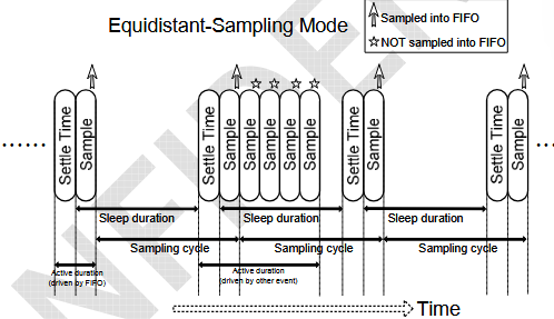
In the low power mode of the STK8327, the G-Sensor actually switches back and forth between the sleep period and the wake-up period: first, it enters the sleep period according to the time period set by parameters, at which point data collection stops and the chip enters an extremely low-power working state; when the sleep time expires or other external events occur, the G-Sensor enters the wake-up period, starts sampling data and stores it in the FIFO, and decides whether to wake up the MCU via an interrupt based on the sampled data; after data sampling ends and the interrupt status is cleared, it re-enters the sleep period. In Low Power working mode, the STK8327 provides two working timings for the wake-up period: EDM and ESM. The main difference lies in the logic by which the G-Sensor samples data and stores it into the FIFO during the wake-up period. Which mode to use depends on how the MCU side utilizes the historical data in the G-Sensor FIFO to implement detection and decision algorithms. EDM: Event Driven Mode. In this timing mode, all data sampled by the G-Sensor during the low-power wake-up period is stored in the FIFO. Note that if other types of events occur, the duration of the G-Sensor being in the wake-up period may be extended, meaning the time interval between consecutive G-Sensor samples saved in the FIFO will not be fixed. Therefore, this mode is more suitable for applications that do not rely on FIFO-cached historical data.
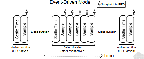
ESM: Equidistant-Sampling Mode. As the name suggests, under this working timing, the time interval of consecutive sample data stored by the G-Sensor in the FIFO is always constant. If the MCU side needs to rely on historical data in the FIFO to implement certain decision algorithms, this working mode is normally more appropriate. As seen in the figure below, if the G-Sensor enters the wake-up period, even if there are multiple data samples, only the sample data from a fixed time period (upward arrow) is saved to the FIFO, while other sample data (pentagram) are discarded. This mode is more suitable for product applications that rely on FIFO historical data to execute algorithmic judgments.
References
- G-sensor Overview and Common Chip Compilation - Jianshu
- STK8327 datasheet