Fundamental Phase Modulation Techniques: BPSK, QPSK, and DQPSK
- 03 Jan, 2025
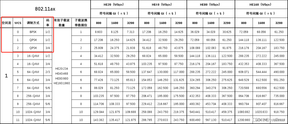
Carrier modulation methods that manipulate phase, such as BPSK and QPSK, are widely used in wireless communications today. The lower-specification MCS (Modulation and Coding Scheme) included in various Wi-Fi standards almost universally employs phase modulation techniques like BPSK and QPSK.
BPSK: Binary Phase Shift Keying
BPSK is the simplest form of phase modulation, where “Binary” indicates the use of 0-degree and 180-degree phases to represent logical 0 and logical 1, respectively. In other words, each carrier symbol in BPSK transmits one bit of baseband data.
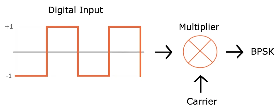
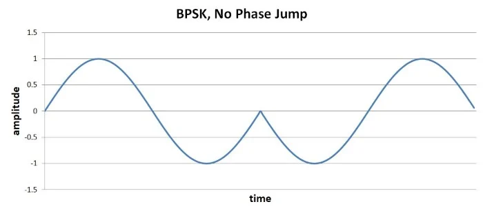
In terms of practical implementation, logical 0 and 1 (or 0-degree and 180-degree phases) are realized by multiplying the sinusoidal carrier wave by +1 or -1, as illustrated in the figure below:
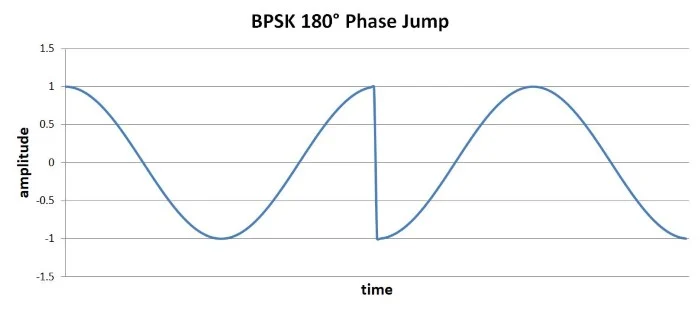
However, several practical details must be considered: during the transmission of a BPSK-modulated carrier, at what phase should the carrier switch? For instance, as shown in the diagram below, if the carrier switches instantly from its maximum amplitude to its minimum amplitude, it causes a “high slope transition” problem. Sharp changes in carrier amplitude radiate high-frequency energy into other frequency bands, causing interference with communications in those bands. Therefore, changes in carrier amplitude should be as smooth as possible to avoid such high slope transitions.
A more reasonable approach is to perform the phase transition at the zero-crossing points of the carrier wave. In this way, when the baseband signal transitions between 0 and 1, the carrier amplitude does not experience abrupt jumps, thereby preventing the scattering of high-frequency energy.
QPSK: Quadrature Phase Shift Keying
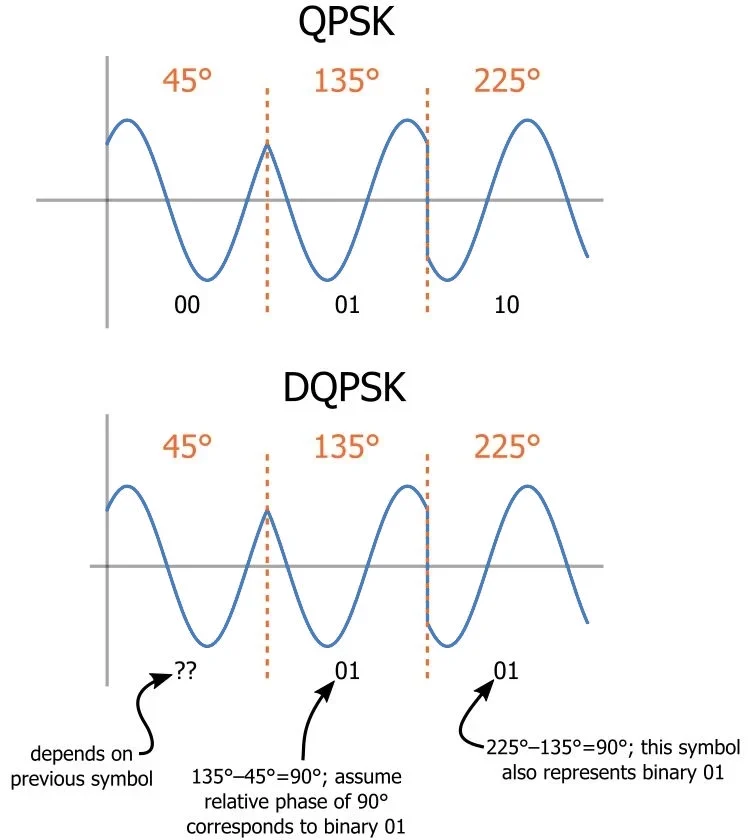
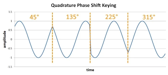
While BPSK transmits one bit of baseband data per carrier symbol, QPSK can transmit two bits of data per symbol. Therefore, each carrier symbol in QPSK modulation can correspond to one of four baseband information pairs: 00, 01, 10, and 11. Each pair corresponds to a different phase of the carrier, with a 90-degree difference between adjacent phases: 45 degrees, 135 degrees, 225 degrees, and 315 degrees.
The biggest advantage of QPSK over BPSK is, of course, a higher transmission rate. If the frequencies of the carrier and baseband signals are kept constant, QPSK carries twice the amount of baseband data per symbol compared to BPSK, effectively doubling the actual data transmission rate under the same conditions. The trade-off, however, is the increased complexity of the QPSK system.
The High Slope Transition Problem in QPSK
As seen in the figure above, when switching between the 45-degree and 135-degree carrier states, the amplitude does not experience a sudden jump. However, during subsequent transitions—such as from 135 degrees to 225 degrees—a noticeable carrier amplitude jump occurs (the aforementioned high slope transition problem). This issue cannot be resolved simply by using BPSK’s zero-crossing switching strategy, because the phase difference in QPSK is 90 degrees rather than 180 degrees. Therefore, other methods are required to address this problem. One common solution is to adopt Offset QPSK (OQPSK), $\pi/4$-QPSK, or techniques similar to MSK/MFSK. The underlying logic of all these approaches is to introduce specific time delays between consecutive carrier symbols to prevent excessively large jumps in carrier amplitude.
DQPSK: Differential QPSK
The challenge with PSK demodulation lies in the fact that it is more difficult to make demodulation decisions compared to FSK. For FSK demodulation, one only needs to measure the carrier frequency to determine whether the modulated baseband information is 0 or 1. For PSK, however, the distinction between 0 and 1 lies in the initial phase. If the initial phases of the modulator and demodulator are not synchronized or slightly misaligned, it can affect the decision-making process in PSK demodulation. To deal with the potential issue of carrier phase asynchrony between the transmitter and receiver, Differential QPSK (DQPSK) was developed.
For standard PSK demodulation, after receiving the RF signal, the local carrier used by the receiver for demodulation must be strictly synchronized in both frequency and phase with the carrier used for PSK modulation at the transmitter; otherwise, the baseband signal cannot be successfully and correctly demodulated, leading to demodulation errors. Thus, PSK demodulation relies on determining the absolute phase of the received signal.
When using DQPSK for modulation and demodulation, absolute phase determination is no longer required. As a result, it is only necessary to ensure that the carrier frequencies of the transmitting modulator and receiving demodulator are identical, without requiring them to share the same phase. DQPSK demodulation for each symbol does not rely on absolute phase judgment, but rather on the phase difference and change between the current symbol and the previous symbol (hence the term “Differential”). In other words, the baseband information carried by each carrier symbol depends on its phase difference relative to the preceding symbol. For example, if there is no phase difference between two consecutive symbols, it indicates that the current symbol carries the baseband data 0b00; if the phase difference is 90 degrees, the current symbol carries 0b01, and so on. Modulating and demodulating in this manner eliminates the strict requirement for identical carrier frequencies and phases imposed by standard PSK/DPSK systems.