Working Principle of IQ Modulation in Wireless Digital Communication
- 27 Dec, 2024
IQ modulation is the foundation of various high-order modulation schemes widely used in LTE and Wi-Fi, such as BPSK, QPSK, 16-QAM, 64-QAM, and 256-QAM. Understanding the working principle of IQ modulation is crucial to grasping the underlying OFDM implementation mechanism in LTE and Wi-Fi. This is because on each subcarrier of OFDM, the final modulation method used is still various QAM techniques based on IQ modulation. In essence, the implementation of OFDM is the superposition of IQ modulations carried out across multiple mutually orthogonal subcarriers.
I and Q in IQ Modulation and the Basic Working Principle of IQ Modulation/Demodulation
The “I” and “Q” in IQ modulation stand for In-Phase and Quadrature, respectively. From a purely literal standpoint, naming these two signals “I” and “Q” seems arbitrary. What does “in-phase” mean? What does “quadrature” mean? What is the reference signal used to determine in-phase and quadrature? In practice, a set of cosine and sine waves of the same frequency is generally used as the I and Q signals. The cosine signal, serving as the I signal, is actually the reference signal, making it naturally the “In-Phase” signal. Meanwhile, the sine wave (which is a cosine wave phase-shifted by 90 degrees at the same frequency) naturally becomes the “Quadrature” signal. Therefore, the simplest way to understand IQ modulation signals is to think of the I signal as the cosine carrier signal and the Q signal as the sine carrier signal, which is at the same frequency but 90 degrees out of phase with the I signal.
So-called IQ modulation uses a set of co-frequency I (cosine) and Q (sine) signals—which are orthogonal to each other with a 90-degree phase difference—as carriers. Two separate baseband signals are modulated onto these two carriers simultaneously. The resulting modulated signals are then superimposed (summed) together and transmitted via RF circuitry. After receiving the RF signal, the receiver performs IQ demodulation. During this process, because the two carriers are mutually orthogonal, the receiver can separate the two baseband signals from the mixed signal based on the I and Q carrier signals used in the modulation process, and demodulate them individually. This is the fundamental working principle of IQ modulation and demodulation.
The diagram below illustrates the basic working principle of IQ modulation.
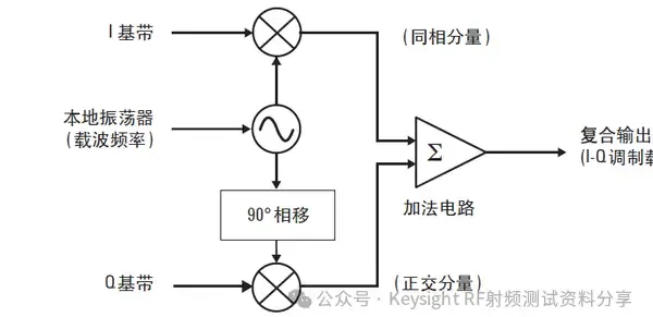
- Before IQ modulation takes place, the baseband digital sequence is sequentially split into two independent baseband modulation signals: the I baseband signal and the Q baseband signal. Then, the I and Q baseband signals are respectively modulated onto the I carrier signal (cosine) and the Q carrier signal (sine). These two modulated signals are then combined using an adder to generate the final IQ-modulated signal, which is transmitted via the RF module and antenna.
The diagram below illustrates the basic working principle of IQ demodulation.
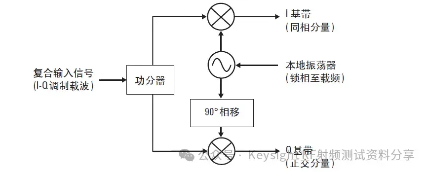
- Once the receiver’s antenna and RF circuitry receive the RF signal, they demodulate it using the same I and Q local carrier signals that were used during modulation, thereby recovering the independent I and Q baseband signals.
Superposition of I and Q Signals
The key to IQ modulation lies in the amplitude and phase changes produced by the superposition of the I and Q signals.
For example, the diagram below shows the superposition of an I signal and a Q signal with identical amplitudes: the orange wave represents the cosine I signal, the blue wave represents the sine Q signal, and their equal-amplitude superposition produces the red signal shown in the figure.
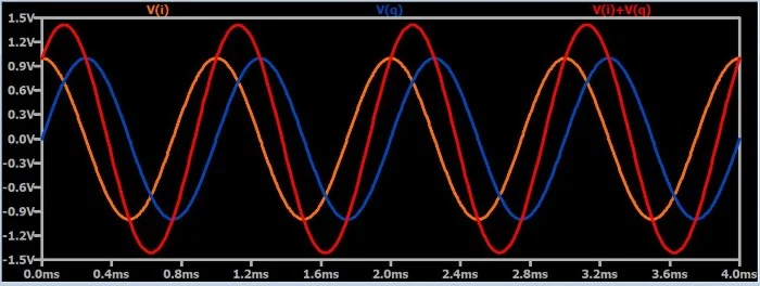
As can be seen, the phase of the signal generated by superimposing equal-amplitude I and Q signals lies exactly between the two signals, which is 45 degrees relative to the I signal.
If you increase or decrease the amplitude of either the I or Q signal, it will not only alter the amplitude of the resulting modulated signal but will also change its phase accordingly.
For instance, in the diagram below, if the amplitude of the I signal (orange) is set to 2 while the amplitude of the Q signal (blue) remains 1, the amplitude of the resulting modulated signal (red) is slightly larger than that of the I signal, and its phase shifts toward the I signal.
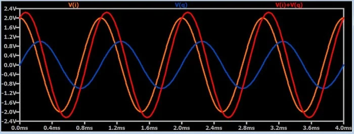
On the other hand, if the amplitude of the I signal (orange) is kept at 1 and the amplitude of the Q signal (blue) is increased to 2, the amplitude of the resulting IQ-modulated signal (red) becomes slightly larger than that of the Q signal, and its phase shifts toward the Q signal.
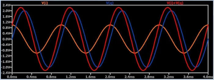
Thus, the conclusion is that for the I and Q signals in IQ modulation, increasing the relative amplitude of one signal not only increases the amplitude of the modulated signal but also causes its phase to shift toward the side with the larger amplitude. Therefore, in essence, IQ modulation consists of separate amplitude modulations on the I and Q paths. However, the result of this modulation affects both the amplitude and the phase of the generated signal.
However, no matter how the amplitudes of the I and Q signals change or combine in the examples above, the phase of the resulting IQ-modulated signal will always vary between 0 degrees (I signal) and 90 degrees (Q signal). How do we achieve a phase variation across the entire 0 to 360-degree range? For schemes like QPSK, 16-QAM, and higher-order QAM, the phases must span from 0 to 360 degrees.
Explaining IQ Modulation Phase Variation Using QPSK
QPSK, or Quadrature Phase Shift Keying, means that each modulation symbol transmits two bits of baseband information on the carrier. The four combinations of two bits (00, 01, 10, 11) correspond to phase modulation angles of 45, 135, 225, and 315 degrees, respectively.
The diagram below shows a block diagram of a QPSK modulator:
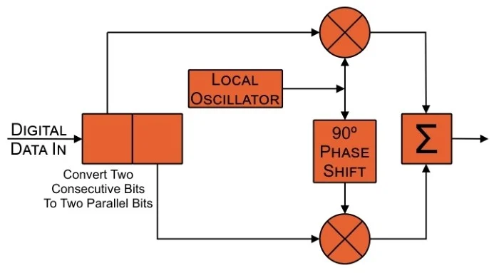
- First, the baseband digital sequence is grouped into 2-bit symbols. Each time, 2 bits of information are fed into the QPSK modulator: 1 bit is modulated onto the I signal, and the other is modulated onto the Q signal. The carrier signal generated by the Local Oscillator (LO) in the diagram above is the I carrier signal. Passing this I carrier signal through a 90-degree phase shift yields the Q carrier signal, which serves as the modulation carrier for the other baseband bit.
- After the two baseband bit signals are modulated onto their respective carrier signals via multipliers (which is essentially two independent amplitude modulation processes), the two modulated carrier signals are superimposed. This generates the final QPSK modulated signal, which is transmitted through the RF circuitry and antenna.
In the process of QPSK modulation, the core operation is essentially performing amplitude modulation on both the I and Q paths. In this amplitude modulation process, if the baseband signals are restricted to only 0 and positive numbers, the amplitude modulation effectively becomes OOK (On-Off Keying), meaning the phase offset of the combined I and Q paths would be restricted to 0 to 90 degrees. However, if we map the baseband bit sequences so that amplitude modulation can support negative numbers (which in practice means inverting the phase of the I and Q signals by 180 degrees), then there are four possible scenarios for the amplitude modulation on the I and Q paths based on their positive/negative relationship.
Scenario 1: Both I and Q Paths Have Positive Amplitude Modulation
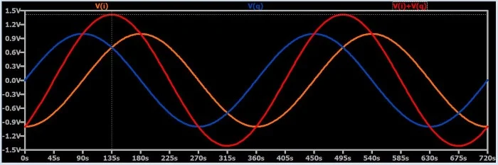
Consistent with the logic described earlier, the phase of the generated IQ-modulated signal varies between 0 and 90 degrees. For QPSK, this corresponds to the modulation state where I = 1 and Q = 1, yielding a phase of 45 degrees.
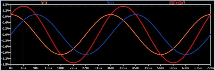
Scenario 2: Positive Amplitude on I Path, Negative Amplitude on Q Path
In this scenario, the phase of the I path remains unchanged while the phase of the Q path shifts by 180 degrees. This causes the phase of the generated IQ-modulated signal to fall between 270 and 360 degrees. For QPSK, this corresponds to the modulation state of I = 1 and Q = -1, yielding a phase of 315 degrees.
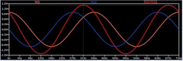
Scenario 3: Negative Amplitude on I Path, Positive Amplitude on Q Path
In this scenario, the phase of the I path shifts by 180 degrees while the phase of the Q path remains unchanged. This causes the phase of the generated IQ-modulated signal to fall between 90 and 180 degrees. For QPSK, this corresponds to the modulation state of I = -1 and Q = 1, yielding a phase of 135 degrees.
Scenario 4: Both I and Q Paths Have Negative Amplitude Modulation
In this scenario, the phases of both the I and Q paths shift by 180 degrees. This causes the phase of the generated IQ-modulated signal to fall between 180 and 270 degrees. For QPSK, this corresponds to the modulation state of I = -1 and Q = -1, yielding a phase of 225 degrees.
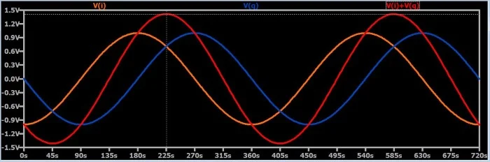
Thus, whether for QPSK or various QAM schemes, the end result is achieved by mapping baseband bit sequences to positive or negative amplitudes for modulation on the I and Q paths, thereby achieving full 360-degree phase modulation.
References
- Understanding I/Q Signals and Quadrature Modulation | Radio Frequency Demodulation | Electronics Textbook
- Why is IQ Modulation Called I and Q? How Does IQ Modulation Work? Must an IQ Modulated Signal Use IQ Demodulation? Principles of IQ Modulation
- Digital Phase Modulation: BPSK, QPSK, DQPSK | Radio Frequency Modulation | Electronics Textbook
- Understanding Quadrature Demodulation | Radio Frequency Demodulation | Electronics Textbook