Detailed Summary of BLE Frequency Hopping Mechanism and Workflow Implementation
- 10 Dec, 2024
Connection Event and Connection Interval
To understand the workflow of the BLE frequency hopping mechanism, one must first understand the concepts of connection events and connection intervals. This is because communication between BLE devices after a connection is established performs frequency hopping operations on a per-connection-event basis.
Once two BLE devices establish a connection, the communication time between them is divided by the connection interval into individual connection events.
The specific connection interval parameter is negotiated during the connection request when the two BLE devices establish a connection. Theoretically, this time period ranges from 7.5 ms to 4 s, with a step unit of 1.25 ms.
Each connection event is always initiated by the master (i.e., the central device). The master sends a data packet to the slave (i.e., the peripheral device), and the slave returns a response packet to the master.
The diagram below illustrates various scenarios within a connection event, including empty packet exchange between the central and peripheral devices (even if there is no data communication requirement, an empty packet must be sent and received to maintain the connection), the central device sending data, the central device reading data from the peripheral device, and bidirectional data transmission between the central and peripheral devices.
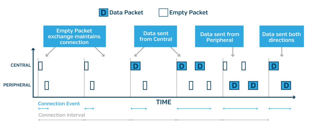
- If there is more communication data to send and receive after the initial communication interaction between both parties, the master sends another data packet to the slave, and the slave returns a response packet, repeating this cycle. Therefore, multiple BLE packets can be transmitted within a single connection event. However, different BLE hardware devices and operating systems have different regulations on the maximum number of BLE packets that can be transmitted in a single connection event. Consequently, if there is a large amount of data to be sent and received between two devices, it needs to be sequentially split across multiple connection events for communication.
- Within each connection event, every communication interaction is initiated by the central device sending a data packet, followed by the peripheral device returning an acknowledgment packet. When multiple packets need to be sent and received within a connection event, the transmission and reception flow on both ends always follows a repeating sequence of Central-Peripheral-Central-Peripheral-…. If situations occur such as the central device having no data to send, the peripheral failing to receive the data packet sent by the central, the peripheral failing to return a response packet for various reasons, or the central device failing to receive the response packet returned by the peripheral, the communication between the two BLE devices in the current connection event is interrupted. The TX and RX of both devices are then turned off to reduce power consumption, waiting to retry in the next connection event cycle.
- Even if there is currently no data to be sent or received between two BLE devices communicating, an empty packet must be exchanged at the beginning of each connection event to synchronize the communication clocks between them.
Communication between BLE devices after a connection is established performs frequency hopping operations based on connection events. That is, in each independent connection event, the central and peripheral devices consistently maintain interaction and communication on the same BLE channel. Once the time period for the next connection event arrives, both devices simultaneously switch to the next channel for communication within the subsequent connection interval time period.
The connection interval parameter, along with the working logic of how both parties select and switch to a new BLE channel after each connection event ends, is negotiated through the connection parameters when the two devices establish a connection.
BLE Connection Establishment Parameters
The establishment of a BLE connection always begins with the central device initiating a connection request packet to the peripheral device.
In advertising mode, the peripheral device periodically and cyclically sends out advertising packets on the three advertising channels 37, 38, and 39. After sending each advertising packet, it opens its RX to listen to the channel for a period of time, and then switches to the next channel to continue advertising. Before establishing a connection, the central device must first listen for advertising packets on the advertising channels. Upon receiving an advertising packet from the target peripheral device, it sends a connection request to the peripheral device to attempt connection establishment.
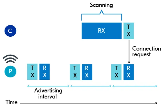
During the connection process where two devices attempt to establish a connection, they negotiate the communication connection parameters to be used afterward. Below is a summary and explanation of the connection parameters related to the frequency hopping mechanism and the packet transmission/reception logic of both communicating parties:
Connection Interval
The connection interval was explained in detail in the previous section. It is the period length of the connection events for communication between the central device and the peripheral device after a BLE connection is successfully established.
In other words, during BLE connection communication, both communicating parties wake up once every connection interval, send and receive a few data packets between them, and then re-enter a sleep state until the next connection interval cycle arrives. In this scenario, the TX and RX of the communication devices remain in a sleep state for the vast majority of the time, thereby achieving low-power operation characteristics.
Supervision Timeout
During the establishment of a BLE connection, a supervision timeout time parameter is also negotiated. This parameter defines the judgment criteria for communication timeout between both parties. For both central and peripheral devices, if the time elapsed since successfully receiving the last data packet from the peer exceeds the duration specified by the supervision timeout, the current connection is considered dropped, and subsequent communication will require rescanning advertising packets and re-establishing a connection.
The supervision timeout parameter is used to allow either the central or peripheral device to recover from a communication failure state in the event of an anomaly (such as a runtime crash, battery depletion, or moving out of signal coverage).
Peripheral Latency
Based on the connection events described above, even when there is no data to send or receive, the central and peripheral devices still need to initiate an empty packet interaction at the beginning of each connection event by the central. However, if there is no data to send or receive between the two devices for an extended period, performing an empty packet interaction at every connection event would significantly impact BLE’s power-saving characteristics.
Therefore, when establishing a connection between the central and peripheral devices, both parties also negotiate a peripheral latency parameter. This parameter specifies the maximum number of connection events the peripheral device can skip waiting to receive and respond to empty packet data from the central when the peripheral has no data to send. With peripheral latency configured, the peripheral device does not need to listen to and respond to data packets from the central in every connection event when it has no data to output; it only needs to send a response packet to the central every few connection events to maintain the communication link between them (provided, of course, that this time does not exceed the aforementioned supervision timeout duration).
For the peripheral device, the peripheral latency parameter results in better low-power and power-saving characteristics because it does not need to wake up to receive and respond to data packets in every connection event. However, this undoubtedly degrades real-time communication performance. If the central device has data to send to the peripheral, it must wait until the communication cycle of the connection event specified by peripheral latency for the peripheral device to have the opportunity to receive and respond to this data. Therefore, the specific setting of this parameter requires a trade-off between power conservation and real-time responsiveness.
Channel Map
The Channel Map information occupies 5 bytes in the connection request packet negotiated during BLE connection establishment. Each bit in these 5 bytes represents the health status of a BLE channel. Therefore, the Channel Map is a list shared between the central and peripheral devices indicating the condition of the 40 BLE communication channels in the current wireless environment, which determines the available communication channels for the frequency hopping algorithm after the subsequent BLE connection is established.
Each bit of the Channel Map is used to mark the availability status of that channel: used indicates that the channel can be used for subsequent communication, while unused indicates that the channel should not be used for subsequent communication.
Hop Increment
Hop Increment is a random value negotiated by both communication parties when a BLE connection is established, with a value ranging from 5 to 16.
The Hop Increment is used in the BLE frequency hopping channel selection algorithm. The central device and the peripheral device independently calculate the BLE communication channel that should be used for each connection event using the same frequency hopping channel selection algorithm, Hop Increment parameter, and Channel Map. Because the channel selection algorithm, Hop Increment, and Channel Map are identical for both, the channels selected by the central and peripheral devices for each connection event after connection will definitely be consistent; otherwise, stable communication would be impossible.
Channel Selection Logic for BLE Connected Frequency Hopping Communication
As described above, after a BLE connection is established, the two devices perform frequency hopping operations between different communication channels based on the previously negotiated Connection Interval period. Each Connection Interval communication cycle uses a different channel for communication, avoiding the impact of complex wireless interference in the 2.4 GHz band on communication stability.
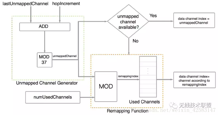
The frequency hopping algorithm between devices across channels is: unmappedChannel = (lastUnmappedChannel + hopIncrement) mod 37.
lastUnmappedChannel is the channel number used by the two devices in the current Connection Event cycle; hopIncrement is the frequency hopping step parameter negotiated by both during connection establishment, with a value ranging from 5 to 16; unmappedChannel represents the channel that should be used for communication between the two in the next Connection Event.
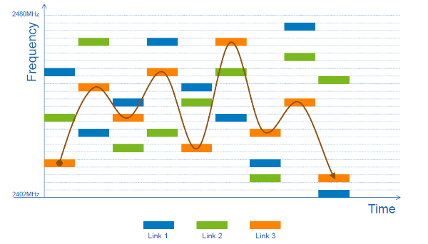
Considering the diverse range of RF communication applications operating in the 2.4 GHz band, severe interference issues exist in this frequency band. Some channels may overlap with the operating frequency bands of routers present in the current environment. If BLE communication continues to use these channels after establishment, it will inevitably lead to severe wireless signal conflicts. Therefore, the BLE frequency hopping algorithm also provides a Channel Map mechanism to further screen available BLE channels in the current environment. The Channel Map parameter is synchronized between the two devices during the BLE connection establishment process, marking the availability of all BLE communication channels with a length of 5 bytes.
If the communication channel calculated according to the above frequency hopping algorithm is marked as an available channel by the Channel Map parameter, that channel is used for communication in the next connection event. However, if the next hop channel calculated by the frequency hopping algorithm is marked as unavailable by the Channel Map parameter, further processing must be carried out according to the following channel remap logic.
Unavailable channel remapping algorithm: remappingIndex = unmappedChannel mod numUsedChannels.
In this remapping algorithm, unmappedChannel is the channel number before remapping—essentially the channel number calculated by the frequency hopping algorithm but marked as unavailable by the Channel Map; numUsedChannels is the total number of channels in the Channel Map that are in the available state; remappingIndex is the channel number after remapping. Next, the actual channel number to be used for communication in the next connection event is found from the list of all available channels in the channel map using remappingIndex.
The calculation logic of channel frequency hopping under the entire BLE mode is shown in the figure below:
Frequency Hopping in Advertising Mode
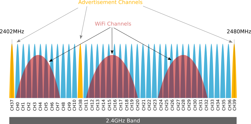
To cope with the complex communication environment present in the 2.4 GHz band, BLE also employs a frequency hopping communication mechanism in advertising mode. Among the 40 channels of BLE, the final three channels—37, 38, and 39—are dedicated exclusively to communication in advertising mode, used for automatic discovery between two devices, assisting in connection establishment, and Beacon mode communications.
As mentioned above, in advertising mode, the peripheral device periodically and cyclically sends advertising packets on these three advertising channels (37, 38, and 39). Frequency hopping advertising across these three advertising channels and the selection of their carrier frequencies are well-designed. As shown in the figure below, the carrier frequencies of the three advertising channels correspond to 2402 MHz, 2426 MHz, and 2480 MHz respectively, which perfectly avoid the spectrum space occupied by the three most commonly used, non-overlapping WiFi channels 1, 6, and 11. This maximally prevents communication on WiFi channels from interfering with the three advertising channels.
References
- Bluetooth® Low Energy Channels - Developer Help
- Ultimate Guide to Managing Your BLE Connection | Punch Through
- Connection process - Nordic Developer Academy
- Brief Analysis of BLE Link Layer Channel Selection Algorithm - Fusheng Wendao - Blog_园
- Analysis of Bluetooth Frequency Hopping Algorithms [Classic Bluetooth vs. BLE 4.x vs. BT 5.0 BLE Section]_BLE Frequency Hopping Algorithm 2-CSDN Blog