Understanding the Basic Concepts of BT.601/BT.656/BT.1120
- 18 May, 2020
To clearly explain the origins of standards like BT.656, BT.601, and BT.1120, we must start with the earliest analog video technology. Early televisions and audio/video signals were acquired, processed, transmitted, and played back in analog form. With the advent of the digital era, the need arose to process analog image and video content using more advanced digital methods, which involved the digitization of analog video. The BT.656, BT.601, and BT.1120 standards define how to achieve this digitization.
PAL and NTSC
Both PAL and NTSC utilize interlaced scanning technology, meaning that a single frame displayed on a monitor is divided into two fields: an even field and an odd field.
Displaying one frame requires the electron gun to scan the CRT twice: first for the odd-numbered lines on the screen, and second for the even-numbered lines (NTSC is the opposite, scanning the even field first, then the odd field). Therefore, a PAL system’s video signal has 25 complete image frames per second, but the electron gun scans 50 times per second; NTSC has 30 complete image frames per second, and the electron gun scans 60 times per second.
In addition to the active image signals displayed on the monitor, PAL or NTSC signals also contain blanking lines and horizontal blanking pixels. These blanking lines and horizontal blanking pixels are not displayed on the screen but are still included in the signal, synchronized by clocks such as line frequency and frame frequency.
Each field’s active image area is surrounded by blanking lines, referred to as the top blanking field and bottom blanking field.
Thus, a single PAL frame (NTSC is similar) consists of the following parts:
- Odd field top blanking;
- Odd field active image data lines;
- Odd field bottom blanking;
- Even field top blanking;
- Even field active image data lines;
- Even field bottom blanking;
Similarly, each data line is composed of two parts:
- Horizontal Blanking Pixels (Horizontal Blanking Interval);
- Active Data;
- PAL system is mainly used in China and Europe. Its detailed technical specifications are as follows:
- Field frequency: 50Hz;
- Frame frequency: 25Hz;
- Line frequency: 15625Hz = 625 lines/frame * 25 frames/second;
- Total lines: 625;
- Total columns: 864;
- Active lines: 576;
- Active columns: 720;
- Aspect ratio: 4:3;
- Pixel sampling frequency: 13.5MHz;
- Sampling time per line: 53.3333us (720/13.5);
- Scanning order: Odd field first, then even field;
- NTSC is mainly used in the United States and Japan. Its detailed technical specifications are as follows:
- Field frequency: 29.97Hz * 2;
- Frame frequency: 29.97Hz;
- Line frequency: 15734.25Hz = 525 lines/frame * 29.97 frames/second;
- Total lines: 525;
- Total columns: 858;
- Active lines: 486 (480);
- Active columns: 720;
- Aspect ratio: 4:3;
- Pixel sampling frequency: 13.5MHz;
- Sampling time per line: 53.3333us (720/13.5);
- Scanning order: Even field first, then odd field;
BT.601
This standard was primarily introduced for the digital conversion and encoding of traditional interlaced analog video signals, defining the specifications and methods for digitizing and encoding the 525-line 60Hz (NTSC) and 625-line 50Hz (PAL) analog video signals described above.
When digitizing PAL and NTSC analog video, the BT.601 standard uses the YCbCr 4:2:2 image digital encoding scheme, with both luminance and chrominance signals quantized to 8 bits per sample;
- The luminance signal (Y) still uses a 13.5MHz sampling frequency, while the chrominance signals (U and V) each use a 6.75MHz sampling frequency. However, because U and V chrominance signals share the Cb/Cr composite signal line for transmission, both utilize a 13.5MHz communication rate in terms of data transfer;
- Sampling data rate: 13.5(MHz) × 8(bit) + 2 × 6.75(MHz) × 8(bit) = 27Mbyte/s.
Regarding the data interface, a 21-pin connection is used for transmission, including 16-bit data. Y signal and UV signal data are transmitted in parallel simultaneously, with independent horizontal and vertical synchronization signals;
- One Y signal, 8-bit;
- One Cb/Cr composite signal, 8-bit;
- System clock signal, horizontal sync signal, vertical sync signal, 1-bit each;
- Two ground lines;
BT.656
BT.656 is essentially an additional data transmission interface and method built upon BT.601. The sampling and quantization of analog video signals still adhere to the definitions of the BT.601 standard.
Based on the data structure specifications provided by BT.601, BT.656 defines two digital interface standards for transmitting digitized video: bit-parallel mode and bit-serial mode.
Bit-parallel mode:
- Uses 9 pins, with 8-bit data transmission and a 1-bit clock signal. Y data is transmitted first, then UV data. There are no independent horizontal and vertical synchronization signals; they are embedded within the data stream.
- Therefore, the transmission clock speed of BT.656 is twice that of BT.601, meaning BT.656’s sampling rate is 27MHz;
Bit-serial mode:
- A single channel transmits a serial multiplexed data stream, where all luminance and chrominance information is time-division multiplexed on the same data line. The bit clock rate approaches 300MHz (actual data transfer rate is 243Mbps), involving complex synchronization, spectral shaping, and clock recovery techniques, which makes it very challenging;
- Therefore, in engineering practice, the bit-parallel mode of BT.656 is generally used.
Since there are no independent horizontal and vertical synchronization signals in BT.656’s bit-parallel mode, how can synchronization information be determined when parsing video signals transmitted via BT.656? This relies on the Start of Active Video (SAV) and End of Active Video (EAV) information embedded within the image data during BT.656 transmission.
A typical line consists of four parts:
- End of Active Video (EAV) code + Horizontal Blanking Pixels (Horizontal Vertical Blanking) + Start of Active Video (SAV) code + Active Video data;
SAV and EAV information both consist of 4 bytes, defined as follows: FF 00 00 XY;
The first three bytes are fixed, while the fourth byte defines information such as line, field, and blanking. This 8-bit byte is defined as follows:
1 F V H P3 P2 P1 P0;
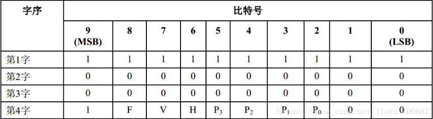
Where:
- F: Marks odd/even field information; 0 for the top field, 1 for the bottom field;
- V: Marks blanking line information; 1 for blanking lines, 0 for active video data lines;
- H: Marks EAV or SAV; 0 for SAV, 1 for EAV;
- P0~P3 are protection bits, whose values depend on F, H, and V, serving for error checking.
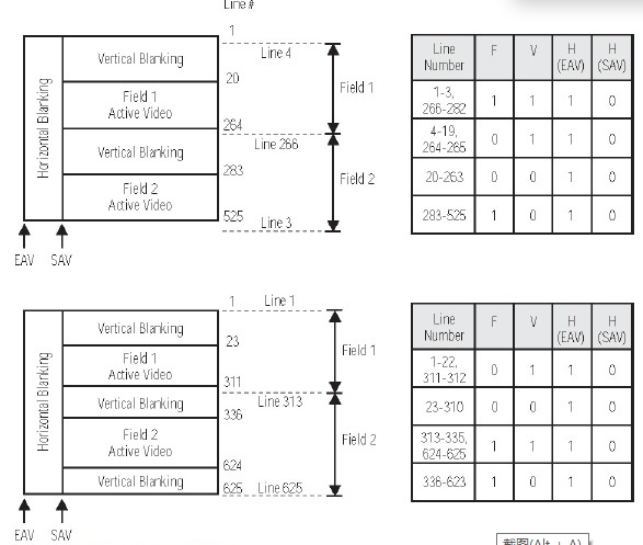
The SAV and EAV settings for each line in NTSC and PAL systems are shown below:
BT.1120
Similar to BT.601/BT.656, the difference is that BT.601/BT.656 define specifications for digital data formats and transmission interfaces for standard-definition NTSC and PAL analog video, whereas BT.1120 targets the digital transmission specification for high-definition analog video with 1080P resolution.
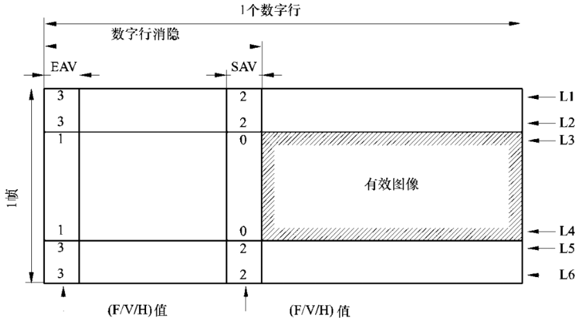
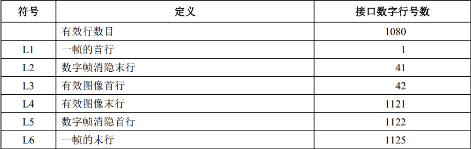
The BT.1120 standard defines that an image frame should contain 1125 total lines and 1080 active lines, with 1920 active pixels per line. It also supports progressive and interlaced scanning frequencies such as 24Hz, 25Hz, 30Hz, 50Hz, and 60Hz.
Below is the frame format definition for progressive scan mode:
Below is the frame format definition for interlaced scan mode:
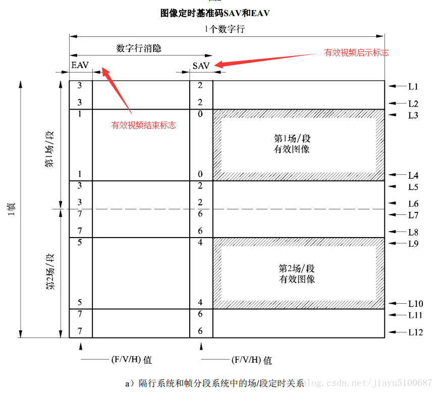
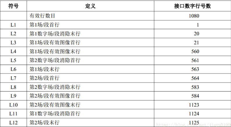
Similarly, mirroring the BT.656 standard, the BT.1120 interface definition does not include discrete horizontal and vertical synchronization signals. Instead, synchronization-related information, such as line, field, and active pixel regions, is embedded within the SAV and EAV information and transmitted to the receiver.
The definitions for SAV and EAV in BT.1120 are also largely consistent with BT.656, meaning that both SAV and EAV information consist of 4 bytes, defined as follows: FF 00 00 XY
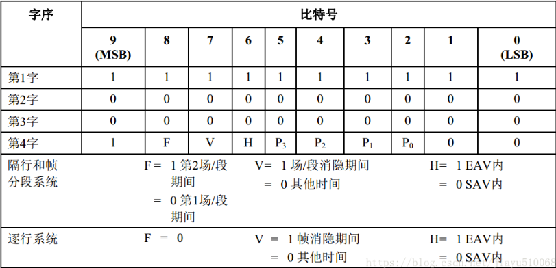
In the last byte XY, the F, V, and H bits respectively represent field identification information, field/frame blanking period identification information, and line blanking period identification information.
The hardware transmission interface definition for BT.1120 is similar to BT.656, supporting two modes: parallel data stream mode and multiplexed parallel data stream mode:
- Parallel data stream mode: vclk + vid[15:0] 16/20bit, simultaneously transmitting 8-bit luminance information and 8-bit chrominance information for one pixel over a 16-bit data bus, similar to using two BT.656 connections combined;
- Multiplexed parallel data stream mode: vclk + vid[7:0] 8/10bit, transmitting pixel luminance and chrominance signals separately on the rising and falling edges of the clock on the same data bus.
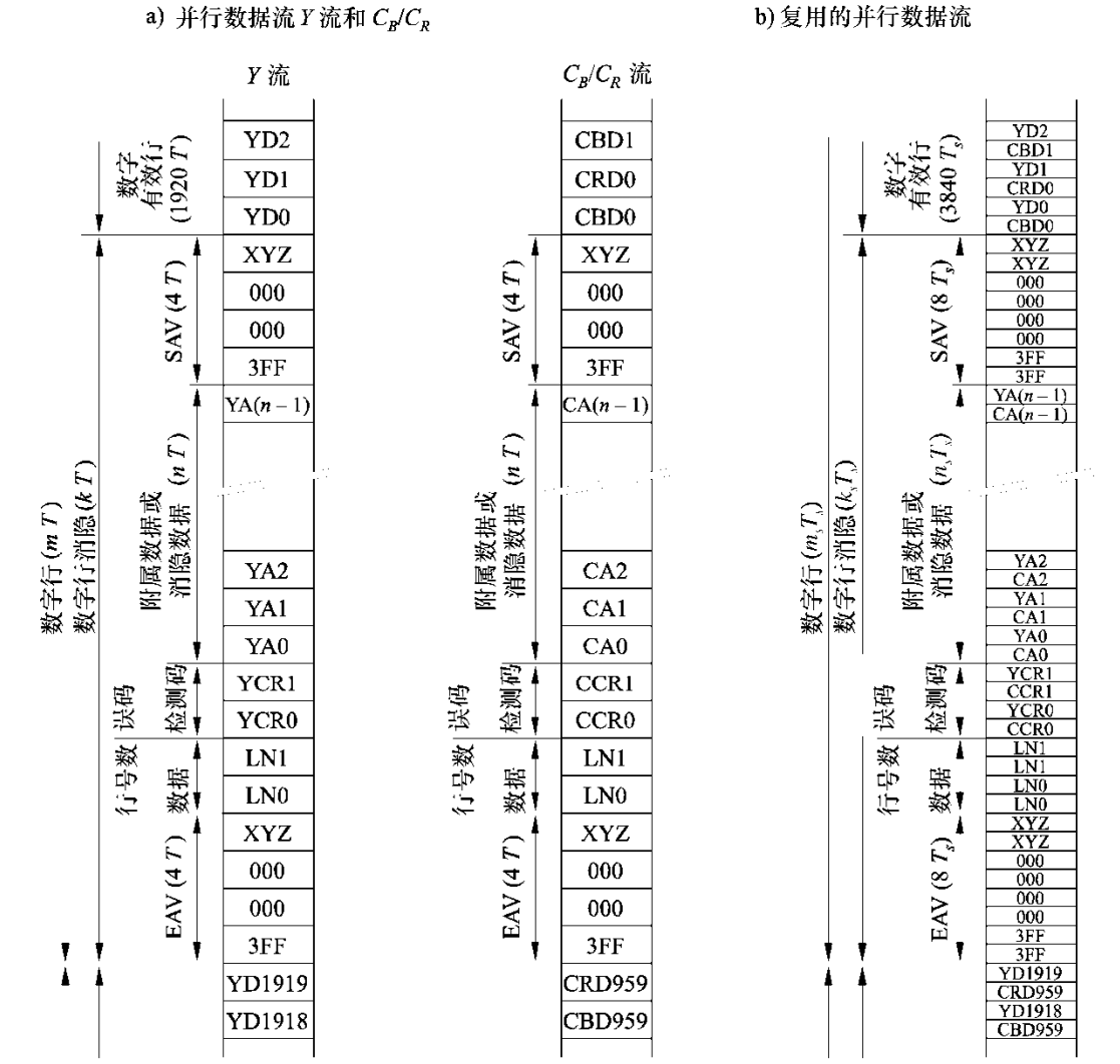
- YD0-YD1919: Digital luminance data Y;
- CBD0-CBD959: Digital chrominance data Cb;
- CRD0-CRD959: Digital chrominance data Cr;
Regarding the vclk frequency, BT.656 has a sampling frequency of 27MHz; whereas BT.1120, designed to support HD resolutions, has a sampling frequency of 72/74.25MHz.
- Specifically, 30fps uses a 74.25MHz sampling rate, while 60fps uses a 148.5MHz sampling rate.